
Simatic S5 Interface Modules
Siemens SIMATIC S5 Interface Modules
Siemens SIMATIC S5 interface modules provide connections between central controllers, expansion racks, distributed I/O stations, programming devices and selected peripheral equipment. This category includes IM rack interfaces, serial interface submodules, PG connection hardware and terminating components. These groups serve different purposes and require different connection arrangements.
Select the hardware using the complete 6ES5 order number, hardware revision, S5 system and device at the other end. Matching connectors do not establish electrical compatibility, protocol support or suitability for the same rack.
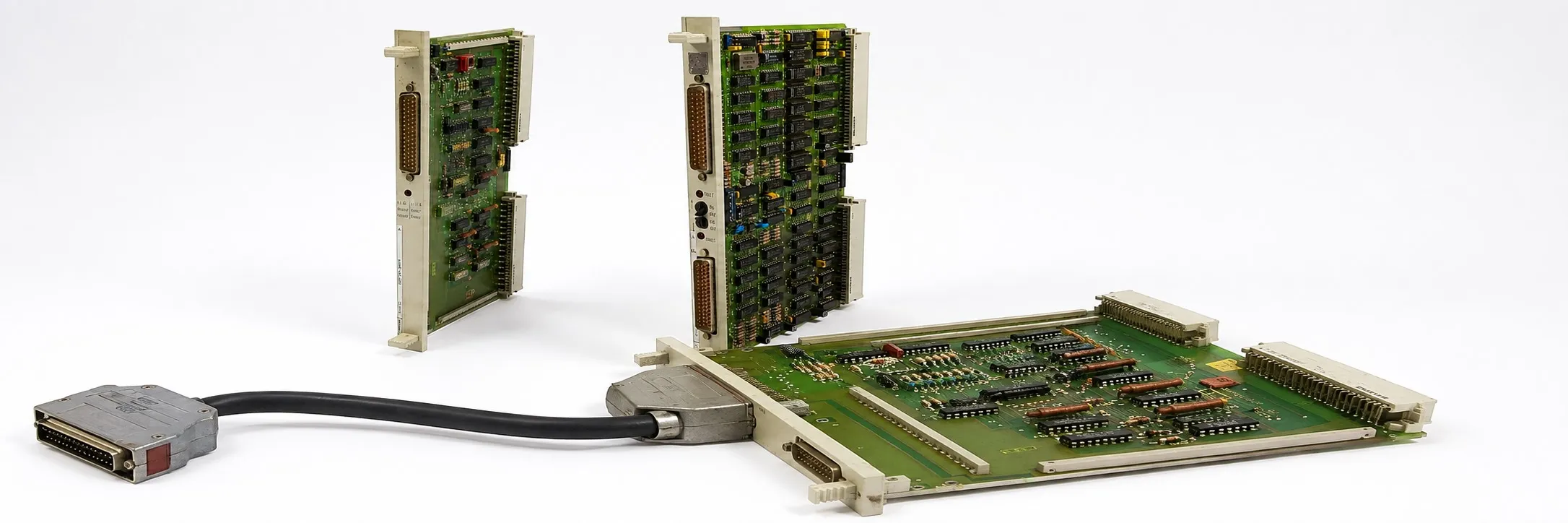
CC, EU and matching interface hardware
CC means central controller and EU means expansion unit. Some arrangements need complementary IM modules at the central and expansion ends. Check the rack, partner module, cable, power distribution and termination together. A distance limit specified for one model cannot be applied to every IM interface.
20 mA TTY, V.24/RS-232 and RS-422/RS-485 describe electrical interfaces; they do not by themselves identify the communication protocol. AS511, SINEC and PROFIBUS functions depend on the CPU, processor, interface submodule and software configuration. An RS-485 connection does not automatically provide PROFIBUS or Modbus compatibility.
IM 300, IM 301 and IM 302 connections
IM 300 models: 6ES5 300-3AB11 · 6ES5 300-5AA12 · 6ES5 300-5CA11 · 6ES5 300-5LB11.
IM 301 models: 6ES5 301-3AB13 · 6ES5 301-5AA12 · 6ES5 301-5AA13 · 6ES5 301-5CA12. IM 302: 6ES5 302-3KA11. Select the centralized or distributed expansion arrangement, partner interface and power supply requirements for the complete model.
IM 310, IM 311 and IM 312 rack interfaces
IM 310 / IM 311: 6ES5 310-3AB11 · 6ES5 310-5AA12 · 6ES5 311-3KA11. Do not select a partner interface by matching number sequences. Use the documented combination for the central and expansion ends.
IM 312-3 models: 6ES5 312-3AB11 · 6ES5 312-3AB12 · 6ES5 312-3AB31 · 6ES5 312-3AB32.
IM 312-5 models: 6ES5 312-5AA13 · 6ES5 312-5AA31 · 6ES5 312-5CA11 · 6ES5 312-5CA12 · 6ES5 312-5CA21 · 6ES5 312-5CA22. Do not assume that all versions share the same integral or separate cable, cable length, mounting arrangement or power conditions.
IM 304 and IM 314 distributed expansion connections
IM 304: 6ES5 304-3UA11 · 6ES5 304-3UA12 · 6ES5 304-3UB11. IM 314: 6ES5 314-3UA11 · 6ES5 314-3UH12 · 6ES5 314-3UR11. Match the central and expansion interfaces, connection cable and any special system version together. Set cable-length jumpers and terminate the line according to the instructions for the actual hardware.
IM 305, IM 306 and IM 307
6ES5 305-7LA11 · 6ES5 305-7LB11 · 6ES5 306-7LA11 · 6ES5 307-0MM11 · 6ES5 307-3UA11. Check each model's rack expansion or transmission function in its own system documentation. Electrical and fiber optic versions require different connection hardware; an optical arrangement also needs the appropriate partner equipment and line conditions.
IM 315, IM 316 and other expansion interfaces
S5-100U IM 315 / IM 316 models: 6ES5 315-8MA11 · 6ES5 316-8FA12 · 6ES5 316-8MA11 · 6ES5 316-8MA12. Follow the system manual for the expansion arrangement, connection orientation and cable selection.
Another expansion model is 6ES5 318-8MA12. The 318 prefix alone does not identify the function. This model must be distinguished from the IM 318-3UA11 and ET 200U interfaces described below.
IM 308 and ET 200U connections
IM 308 models: 6ES5 308-3UA11 · 6ES5 308-3UB11 · 6ES5 308-3UC11 · 6ES5 308-3UC21. For an ET 200 connection, verify the master function, protocol scope, configuration requirements and any required memory hardware against the exact version.
ET 200U interface models: 6ES5 318-8MB11 · 6ES5 318-8MB12 · 6ES5 318-8MB13 · 6ES5 318-8MC12. Supported DP/FMS functions and parameter settings must not be assumed identical. Select the GSD file or other configuration data using the complete order number and revision.
IM 318-3UA11: 6ES5 318-3UA11. Its own manual covers connections involving older central controllers and expansion units. The IM 318 name alone does not make it a replacement for an ET 200U interface.
Special system and peripheral connections
IM 324 models: 6ES5 324-3UA12 · 6ES5 324-3UR11. Select partner hardware and operating conditions for these special system connections using the relevant system documentation.
6ES5 321-0AA11 is a SINEC L1 monitoring adapter, while 6ES5 341-3AA11 is an external memory interface. Legacy PG hardware such as 6ES5 635-0AA11 also needs its specific host equipment and connection documentation; it should not be treated as a general CPU or rack adapter.
ET 200K and CP 541 serve different functions
6ES5 418-8MB11 is an ET 200K compact distributed I/O station. It should not be assessed simply as an IM board connecting two racks. Check its field connections, power supply and master configuration together.
6ES5 541-8AA11 is a CP 541 communications processor. Its SINEC L2 and DP connection functions require the operating modes and parameters specified in its manual. A basic serial port converter should not be assumed to provide the same functions.
Programming device connections and 512 peripheral interfaces
500, 501 and 511 connection hardware: 6ES5 500-7AA12 · 6ES5 501-5AA11 · 6ES5 511-5AA12 · 6ES5 511-5AA14. Identify the legacy PG, PLC and connection cable together. Physical installation alone does not establish compatibility with the programming software.
512 models: 6ES5 512-5AA12 · 6ES5 512-5AA21 · 6ES5 512-5BC12 · 6ES5 512-5BC21. These legacy peripheral interfaces include different basic-board and expansion-board functions. They should not all be labelled as PG adapters. Check the peripheral equipment, board combination and software requirements for the version involved.
752 plug-in interface submodules
752-0AA models: 6ES5 752-0AA12 · 6ES5 752-0AA22 · 6ES5 752-0AA23 · 6ES5 752-0AA42 · 6ES5 752-0AA43 · 6ES5 752-0AA52 · 6ES5 752-0AA53 · 6ES5 752-0AA62.
752-0LA models: 6ES5 752-0LA12 · 6ES5 752-0LA52 · 6ES5 752-0LA62. These submodules provide specific serial or PG connection options in suitable CPUs or processors. Verify the TTY, V.24 or RS-422/RS-485 option, supported protocol and cable against the complete submodule code and host device.
760 terminating components
6ES5 760-0AA11 · 6ES5 760-0AB11 · 6ES5 760-0HA11 · 6ES5 760-1AA11. A terminator is an electrical component, not simply a cover for an unused socket. Its purpose at the end of a line or an applicable unused connection depends on the IM arrangement. Different 760 codes must not be substituted without checking the documentation.
Used equipment and functional checks
For purchasing or a quotation, provide the complete model, quantity, working or faulty condition, label photograph and asking price. Send details of equipment you wish to sell to otomasyonavm@gmail.com. Sales require an invoice; used equipment is sold without returns. Workshop testing may be arranged; an interface test requires a suitable CPU, partner module and cable.
Editor's Note
Before choosing a replacement, look beyond its front panel. Check the complete codes at both ends, the rack and the cable between them. A correct board cannot compensate for an incompatible partner.
A bus fault does not immediately prove that the module has failed. Start with the supply, connector pins, cable and terminator. A loose connection can account for hours of unnecessary troubleshooting.
Before removal, photograph and record the DIP switches, jumper positions and address settings. The replacement's factory settings may differ from the machine's configuration.
An illuminated LED is not a complete communication test. Check data exchange, diagnostics and the required I/O addresses with the appropriate CPU and partner device. Receiving power and performing the required function are separate checks.
When ordering a spare, include the matching cable, connector and terminator where needed. Keep the PG project and configuration records. One missing small part can prevent an otherwise sound replacement from being used.
OtomasyonAVM Resources and PDF Manuals
For system selection, review the SIMATIC S5 CPU families and S5 module categories. Compare the manual's order-number and edition scope with the actual hardware.
+ Shared Siemens SIMATIC S5 PDF archive
+ ET 200K 418-8MB11 / 6ET11 manual — German
+ ET 200U distributed I/O manual — English
+ IM 318-3UA11 manual — English
+ S5-135U/155U system manual — English
+ CP 541 communications processor manual — English
Related Topics
S5 cables and connectors · S5 racks · S5 power supplies · S5 communications modules
Browse SIMATIC S5
Parent S5 module category · SIMATIC S5 CPU options · Siemens S5 PLCs · Used Siemens automation equipment
Siemens and External References
+ Siemens — S5-135U/155U System Manual (English)
+ Siemens — S5-100U System Manual (English)
+ Siemens — IM 318-3UA11 (English)
+ Siemens — ET 200U Distributed I/O System (English)
+ Siemens — CP 541 Communications Processor (English)