
Simatic S5 Function modules
Siemens SIMATIC S5 Function Modules, CPUs and System Hardware
Under Siemens SIMATIC S5 function modules, this page includes CPUs, coordinators, auxiliary supply units, backup batteries, fans and maintenance accessories. A CPU executes the control program; a coordinator participates in multiprocessor system access; supply and cooling components support hardware operation. Identify each part’s role by its complete order number.
Select a spare using the complete 6ES5 code, system family, hardware/software version, program memory and interface arrangement. Establish the SIMATIC S5 CPU family and S5 module structure before considering a replacement. U, F and H systems serve different operating purposes.
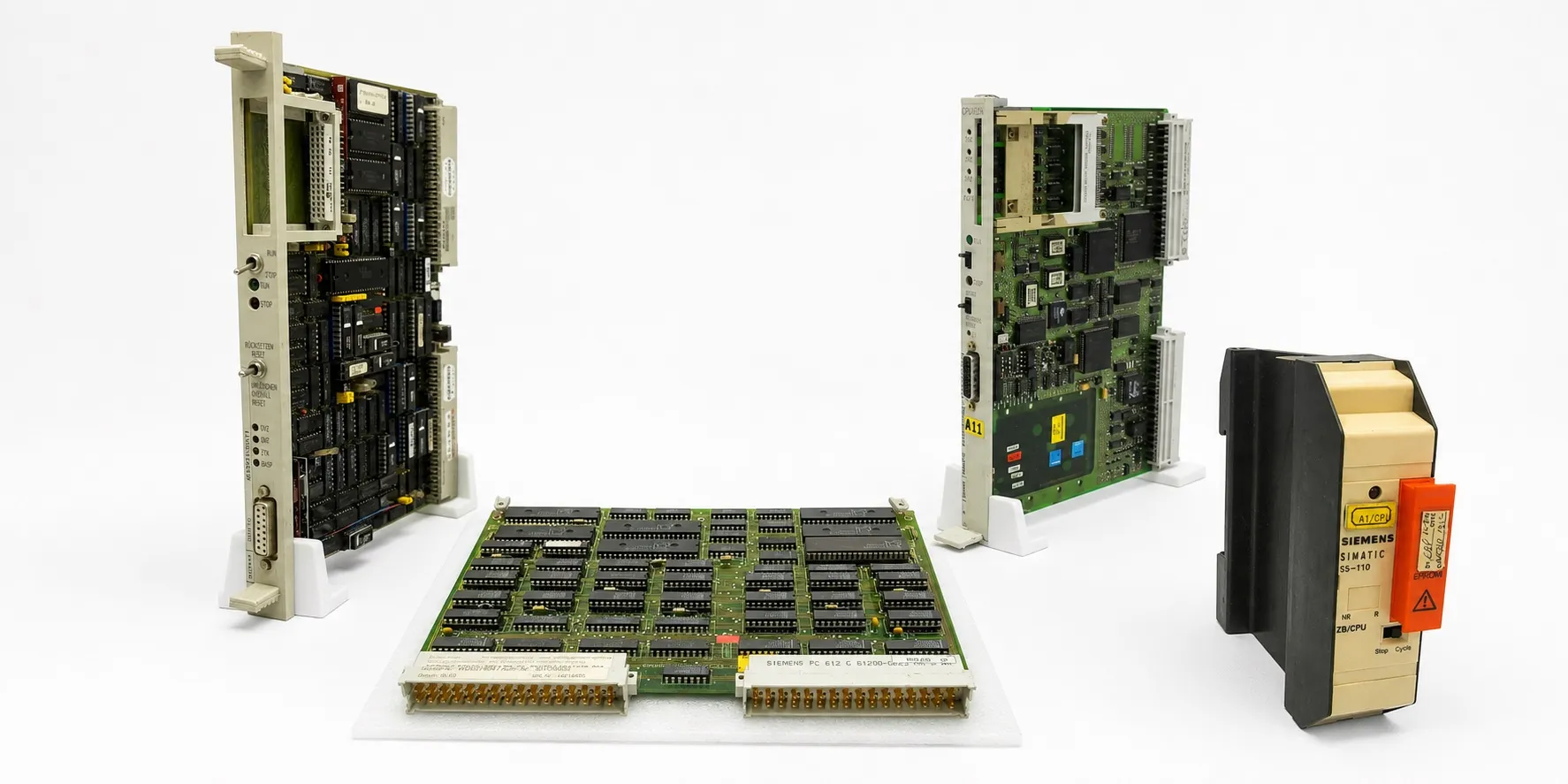
CPU 900, 902 and 905: legacy system hardware
900 group: 6ES5 900-7AB11 · 6ES5 900-7AB21 · 6ES5 900-7AC21 · 6ES5 900-7AD11. 902 group: 6ES5 902-3SA11 · 6ES5 902-3SA12. Match the CPU, program submodule and programming connection for legacy S5-110A and S5-110S equipment. A shared 900 or 902 family number does not establish identical memory or connections across versions.
CPU 905: 6ES5 905-3RB11 · 6ES5 905-3RB21. For these S5-105R processors, distinguish program-element capacity from memory capacity in bytes. Assess program access together with the appropriate programmer and installed program submodule.
CPU 920, 921 and 922
CPU 920: 6ES5 920-3UA11 · 6ES5 920-3UA12. CPU 921: 6ES5 921-1AA21 · 6ES5 921-3UA11 · 6ES5 921-3UA12 · 6ES5 921-3WA13 · 6ES5 921-3WB11 · 6ES5 921-3WB13 · 6ES5 921-3WB14 · 6ES5 921-3WB15. These groups include versions for different central controllers and applications. In particular, 921-1AA, 921-3UA and 921-3W codes must not be treated as one interchangeable spare.
CPU 922: 6ES5 922-3UA11. Older documentation may call it the R processor. Check instructions, memory layout and multiprocessor operation in the applicable CPU manual. Record the fitted S5 memory submodules and existing program backup with the processor.
923 and 923C coordinators
6ES5 923-3UA11 · 6ES5 923-3UC11. A coordinator forms part of the access arrangement between processors and shared resources in a suitable multiprocessor system. Distinguish it from an application CPU or a general communication board. Review its slot, settings and connected processors together.
924, 925, 926 and 927 processor groups
924: 6ES5 924-3SA11 · 6ES5 924-3SA12. 925: 6ES5 925-3KA12 · 6ES5 925-3SA11 · 6ES5 925-5AA12. For legacy 150-family and related central-controller hardware, identify the exact system, installed program and processor arrangement.
926: 6ES5 926-3KA12 · 6ES5 926-3SA11 · 6ES5 926-3SA12 · 6ES5 926-5AA12. 927: 6ES5 927-3KA13 · 6ES5 927-3SA11 · 6ES5 927-5BA12 · 6ES5 927-5BA13. Similar front panels or board dimensions do not establish matching instructions, memory or direct interchangeability. Compare the rack and other installed board numbers as well.
CPU 928, 928A and 928B
928 / 928A group: 6ES5 928-3UA11 · 6ES5 928-3UA12 · 6ES5 928-3UA21. 928B group: 6ES5 928-3UB11 · 6ES5 928-3UB12 · 6ES5 928-3UB21. For these S5-135U/155U processors, check version, program memory and serial-interface capabilities against the model’s technical table.
Assess the second interface slot, fitted interface submodule and available communication function separately. Select S5 interface modules and communication hardware using more than the CPU 928 family name.
S5-115U: CPU 941, 942, 943, 944 and 945
CPU 941: 6ES5 941-7UA11 · 6ES5 941-7UA12 · 6ES5 941-7UA13 · 6ES5 941-7UB11. Standard CPU 942: 6ES5 942-7UA11 · 6ES5 942-7UA12 · 6ES5 942-7UA13 · 6ES5 942-7UB11. Compare usable program memory, the memory submodule and system software between early and later hardware versions.
CPU 943: 6ES5 943-7UA11 · 6ES5 943-7UA21 · 6ES5 943-7UA22 · 6ES5 943-7UB11 · 6ES5 943-7UB21. CPU 944: 6ES5 944-7UA11 · 6ES5 944-7UA12 · 6ES5 944-7UA22 · 6ES5 944-7UB11 · 6ES5 944-7UB21. Interface count, instructions used by the application and installed peripherals affect spare selection alongside memory capacity.
CPU 945: 6ES5 945-7UA11 · 6ES5 945-7UA13 · 6ES5 945-7UA21 · 6ES5 945-7UA23. Loading the program alone does not complete a CPU replacement check. Verify startup behaviour, data blocks, timers, communication and the machine cycle. Instruction count, capacity in KB and installed memory-card capacity are separate values.
Special S5-115F and S5-115H processors
CPU 942F: 6ES5 942-7UF12 · 6ES5 942-7UF14 · 6ES5 942-7UF15. The F system is designed for safety functions. Assess the processor version, partner subunit, system parameters and configuration together. Different UF versions must not automatically be treated as equivalent.
CPU 942H: 6ES5 942-7UH11. The H system is intended for high availability and redundant operation. 942F and 942H have different system roles. Operation of one side alone does not validate the complete redundant system or its switchover behaviour.
CPU 946/947 processor arrangement
Standard 946 modules: 6ES5 946-3UA11 · 6ES5 946-3UA21 · 6ES5 946-3UA22 · 6ES5 946-3UA23. Standard 947 modules: 6ES5 947-3UA11 · 6ES5 947-3UA21 · 6ES5 947-3UA22. Assess the CPU 946/947 arrangement as complementary processor hardware. A single 947 board must not be treated as a complete standalone PLC processor.
946R/947R hardware for H systems: 6ES5 946-3UR21 · 6ES5 947-3UR11 · 6ES5 947-3UR21. Match the partner processor, versions, inter-controller connection and redundancy configuration together. UA and UR codes serve different applications.
CPU 948 and CPU 948R
Standard CPU 948: 6ES5 948-3UA11 · 6ES5 948-3UA12 · 6ES5 948-3UA13 · 6ES5 948-3UA21 · 6ES5 948-3UA22 · 6ES5 948-3UA23. CPU 948R: 6ES5 948-3UR13 · 6ES5 948-3UR21 · 6ES5 948-3UR22 · 6ES5 948-3UR23. Establish program memory, system software and available interfaces from the complete order number.
The 948R belongs to an H-system arrangement. Preserve the system configuration and any relevant COM project data as well as the program backup. Do not apply one model’s RAM capacity or second-interface capability to every 948 version.
932 housing and auxiliary supply hardware
932 housing/power-supply unit: 6ES5 932-3SA12. This powered S5-110S central-controller housing is a separate product from the CPU. State whether a used delivery includes the CPU and other boards.
PS 935: 6ES5 935-8ME11. This module supports suitable Ex analog I/O arrangements and is specified for 24 V DC input and 9 V DC / 2.5 A output. Distinguish it from a standard 24 V field supply and verify system/CPU compatibility separately.
956 auxiliary supply submodules: 6ES5 956-0AA11 · 6ES5 956-0AA12. Their 15 V auxiliary supply function is used within an appropriate main power supply. 958 enable supply: 6ES5 958-4UA11. It forms part of the 24 V enable-supply arrangement for suitable I/O modules. Trace the main S5 power supply, field load supply and enable line separately.
Backup batteries and memory protection cassette
Battery hardware: 6ES5 980-0DA11 · 6ES5 980-0MB11 · 6ES5 980-0NC11. Verify chemistry, voltage, connections and charging requirements against the complete code. The 980-0NC11 is rechargeable battery hardware; backup batteries are not all the same type.
Memory-submodule protection cassette: 6ES5 980-4BA11. This is a case for protecting and transporting a removed submodule. The cassette code does not identify an electronic memory board, its capacity or program contents.
Fans, fan subassemblies and filter hardware
Fan subassemblies: 6ES5 988-3LA11 · 6ES5 988-3NA11. The 3LA11 belongs to an AC-powered arrangement; the 3NA11 uses 24 V DC. Verify the exact input selection on the label and in the applicable manual. Other fan/replacement-fan hardware: 6ES5 988-3NB41 · 6ES5 988-7NA11. Match the mechanical layout and associated power-supply version too.
Filter holder assembly: 6ES5 981-0FA41. Inspect the filter, airflow path and fans together. A rotating fan alone does not establish adequate cooling. Check for a blocked filter, incorrect airflow or a fan-fault indication.
Keyboards, mounting frames and connectors
Process keyboards: 6ES5 982-2AA11 · 6ES5 982-2AB12. Assess these with the connected CP/operator equipment and cable arrangement. Panel mounting frames: 6ES5 982-3UA11 · 6ES5 982-3UB11. A keyboard and a mechanical mounting frame are different product types.
Connector set: 6ES5 983-2AB11. Check the relevant module’s pin arrangement, connector quantity and supplied contents. Suitable S5 cables and connectors and racks and carriers complete the system connection.
984 adapters, carrying case and documentation
984 connection/programming adapters: 6ES5 984-0DA11 · 6ES5 984-1UA11 · 6ES5 984-1UB11 · 6ES5 984-2UA11. Match the DG/PG device, programmer interface and any adapter power supply using the complete code. The 0DA, 1UA, 1UB and 2UA suffixes do not identify one common connection function.
Carrying case: 6ES5 986-0MA11. S5-135U / CPU 922 documentation package: 6ES5 998-1UL13. State the supplied contents of cases, document sets and electronic hardware separately. Related maintenance equipment is listed under S5 supplementary modules and accessories.
Program backup, addressing and functional checks
Before removal, record the program, data blocks, fitted memory submodule, CPU version, switch positions and rack arrangement. Do not assume that the running program matches the EPROM/EEPROM contents. Preserve existing data before considering an overall reset or battery replacement.
After CPU replacement, check digital inputs, digital outputs, analog channels and combined I/O at their assigned addresses. An illuminated input LED alone does not establish that the program reads the correct input byte. Actual addresses depend on the CPU, rack and module arrangement.
Used equipment purchasing and selling
For a quotation, provide the complete model, quantity, working or faulty condition, label photograph, hardware version, included accessories and asking price. Send details of equipment you wish to sell to otomasyonavm@gmail.com. Sales require an invoice; used equipment is sold without returns. Workshop testing may be arranged when a suitable system is available.
Editor's Note
When selecting a spare CPU, go beyond the 942, 928 or 948 marking on its front. Read the complete order number, hardware version and installed system. A small suffix difference can change the required application.
Preserve the program and data blocks before removing a board from a working machine. Photograph the fitted memory submodule too. A machine name on an old EPROM label does not establish that it contains the latest running program.
Do not test F and H hardware as ordinary standalone CPUs. Assess the partner processor, system connections and configuration together. One side reaching RUN does not validate the complete safety function or redundant switchover.
For a battery warning, establish the backup and manufacturer’s replacement procedure before disconnecting anything. Rechargeable batteries and primary cells must not be connected interchangeably.
Look beyond the CPU when investigating a fault. The 5 V supply under load, fans, filters, backplane connectors and contact problems can stop a machine too. Include the filter and fault relay even when the fan rotates.
Establish what is actually supplied: a CPU, empty housing, adapter or protection cassette. Agree the included components and test performed before purchase; missing parts can be difficult to source later.
OtomasyonAVM Resources and PDF Manuals
+ Shared Siemens SIMATIC S5 PDF archive
+ SIMATIC S5 ST 50 catalogue — English
+ S5-115U system manual — English
+ S5-135U CPU 921/922 manual — English
+ S5-135U/155U system manual — English
+ S5-155U CPU 946/947 manual — English
+ S5-115F manual, Volume 1 — English
+ S5-115H system manual — German
+ S5-155H system manual, Volume 1 — English
+ SIMATIC S5 ST 53 catalogue — German
Related Topics
S5 memory cards · S5 interface modules · S5 communication modules · S5 positioning modules
Browse SIMATIC S5
Parent S5 module category · SIMATIC S5 CPU options · S5 supplementary modules · Siemens S5 PLCs · Used Siemens automation equipment
Siemens and External References
+ S5-135U/155U System Manual (English)
+ S5-115F Manual, Volume 1 (English)
Refine Search
- 6ES5 900-7AB11
- 6ES5 900-7AB21
- 6ES5 900-7AC21
- 6ES5 900-7AD11
- 6ES5 902-3SA11
- 6ES5 902-3SA12
- 6ES5 905-3RB11
- 6ES5 905-3RB21
- 6ES5 920-3UA11
- 6ES5 920-3UA12
- 6ES5 921-1AA21
- 6ES5 921-3UA11
- 6ES5 921-3UA12
- 6ES5 921-3WA13
- 6ES5 921-3WB11
- 6ES5 921-3WB13
- 6ES5 921-3WB14
- 6ES5 921-3WB15
- 6ES5 922-3UA11
- 6ES5 923-3UA11
- 6ES5 923-3UC11
- 6ES5 924-3SA11
- 6ES5 924-3SA12
- 6ES5 925-3KA12
- 6ES5 925-3SA11
- 6ES5 925-5AA12
- 6ES5 926-3KA12
- 6ES5 926-3SA11
- 6ES5 926-3SA12
- 6ES5 926-5AA12
- 6ES5 927-3KA13
- 6ES5 927-3SA11
- 6ES5 927-5BA12
- 6ES5 927-5BA13
- 6ES5 928-3UA11
- 6ES5 928-3UA12
- 6ES5 928-3UA21
- 6ES5 928-3UB11
- 6ES5 928-3UB12
- 6ES5 928-3UB21
- 6ES5 932-3SA12
- 6ES5 935-8ME11
- 6ES5 941-7UA11
- 6ES5 941-7UA12
- 6ES5 941-7UA13
- 6ES5 941-7UB11
- 6ES5 942-7UA11
- 6ES5 942-7UA12
- 6ES5 942-7UA13
- 6ES5 942-7UB11
- 6ES5 942-7UF12
- 6ES5 942-7UF14
- 6ES5 942-7UF15
- 6ES5 942-7UH11
- 6ES5 943-7UA11
- 6ES5 943-7UA21
- 6ES5 943-7UA22
- 6ES5 943-7UB11
- 6ES5 943-7UB21
- 6ES5 944-7UA11
- 6ES5 944-7UA12
- 6ES5 944-7UA22
- 6ES5 944-7UB11
- 6ES5 944-7UB21
- 6ES5 945-7UA11
- 6ES5 945-7UA13
- 6ES5 945-7UA21
- 6ES5 945-7UA23
- 6ES5 946-3UA11
- 6ES5 946-3UA21
- 6ES5 946-3UA22
- 6ES5 946-3UA23
- 6ES5 946-3UR21
- 6ES5 947-3UA11
- 6ES5 947-3UA21
- 6ES5 947-3UA22
- 6ES5 947-3UR11
- 6ES5 947-3UR21
- 6ES5 948-3UA11
- 6ES5 948-3UA12
- 6ES5 948-3UA13
- 6ES5 948-3UA21
- 6ES5 948-3UA22
- 6ES5 948-3UA23
- 6ES5 948-3UR13
- 6ES5 948-3UR21
- 6ES5 948-3UR22
- 6ES5 948-3UR23
- 6ES5 956-0AA11
- 6ES5 956-0AA12
- 6ES5 958-4UA11
- 6ES5 980-0DA11
- 6ES5 980-0MB11
- 6ES5 980-0NC11
- 6ES5 980-4BA11
- 6ES5 981-0FA41
- 6ES5 982-2AA11
- 6ES5 982-2AB12
- 6ES5 982-3UA11
- 6ES5 982-3UB11
- 6ES5 983-2AB11
- 6ES5 984-0DA11
- 6ES5 984-1UA11
- 6ES5 984-1UB11
- 6ES5 984-2UA11
- 6ES5 986-0MA11
- 6ES5 988-3LA11
- 6ES5 988-3NA11
- 6ES5 988-3NB41
- 6ES5 988-7NA11
- 6ES5 998-1UL13