
Simatic S5 Digital Input/Output modules
Siemens SIMATIC S5 Digital Input/Output Modules
Siemens SIMATIC S5 digital input/output modules combine field-signal inputs and load-control outputs in the same hardware. The 482 family includes fixed channel arrangements, shared channels usable as inputs or outputs, and models for special safety applications. This page also includes EKL 484 hardware, mounting racks and a related output module.
Select the hardware using the complete 6ES5 order number, input/output count, 24 V DC wiring arrangement, output current, isolation and system compatibility. First identify the SIMATIC S5 CPU family and the required S5 module arrangement.
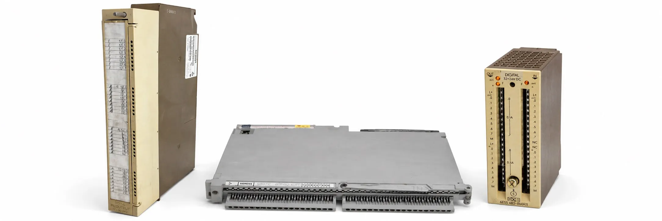
What should be checked on a combined I/O board?
Having inputs and outputs on one board does not mean that every terminal can change direction freely. Identify fixed inputs, fixed outputs and any selectable channels from the model’s wiring diagram. For dedicated functions, also review S5 digital input modules and S5 digital output modules.
482-8MA13: 16 inputs and 16 outputs
6ES5 482-8MA13 is a 24 V DC combined I/O module with 16 digital inputs and 16 digital outputs. Its rated output current is 0.5 A per channel, with a permissible total output current of 6 A. Multiplying the channel rating by 16 does not establish the permissible simultaneous load.
The input and output sections are non-isolated. Check the external field supply, M reference and connector wiring together. The 16 inputs and 16 outputs are monitored in separate input and output address areas.
Earlier 482-8MA11 and 482-8MA12 versions
6ES5 482-8MA11 and 6ES5 482-8MA12 are earlier versions within this family. Verify output-group current ratings, hardware revision and wiring in their own documentation. Do not automatically apply the 8MA13 channel and total current ratings to either model.
482-4UA11 and 482-4UA20: selectable I/O channels
6ES5 482-4UA11 and 6ES5 482-4UA20 have 32 physical channels: 16 fixed inputs, 8 fixed outputs and 8 channels usable as inputs or outputs. 16 inputs/16 outputs and 24 inputs/8 outputs are the two endpoints of this allocation. Define selectable-channel use together with the program and wiring.
A key model difference is that 4UA11 includes an interface for the IP 257; 4UA20 does not. This can affect replacement selection despite a similar channel arrangement. Record the common isolation group, enable connections and the assigned function of each configurable terminal.
482-7LA11: standard input/output functions
6ES5 482-7LA11 provides 16 inputs and 16 outputs at 24 V DC, with 0.5 A outputs. It uses positive-signal inputs and positive-switching outputs. Check supply references for the input/output groups, simultaneous load limits and system addressing.
482-7LF11 and 482-7LF21: safety-output read-back
6ES5 482-7LF11 has inputs reading M potential and outputs supplying P potential; 6ES5 482-7LF21 has inputs reading P potential and outputs switching to M potential. Both models have 16 inputs and 16 outputs, with a rated output current of 0.5 A.
The S5-115F manual defines these inputs for reading back the other subunit’s 24 V safety-related outputs. Assess read-back wiring, module pairing and the safety program together. Illuminated LEDs or standalone output operation do not validate the safety function.
482-3BA11 and 482-3BE11
6ES5 482-3BA11 and 6ES5 482-3BE11 are legacy 482 hardware. Match the CPU family, input/output arrangement, front connector and load supply using the complete order number. Do not transfer 4UA, 7LF or 8MA wiring ratings to a 3BA or 3BE board.
484-8AD11: EKL 484 electronic terminal-strip system
6ES5 484-8AD11 is a 24 V DC I/O module with 8 inputs and 8 outputs for the EKL 484 electronic terminal-strip system. Select it together with the EKL connection hardware, system interface and field supply. Its mounting and bus connections must not be assumed identical to those of a 482 rack-mounted board.
710 mounting racks
S5-110 family racks: 6ES5 710-0SA11 · 6ES5 710-0SA41. S5-110A racks: 6ES5 710-0AA11 · 6ES5 710-0AA41. These are mounting racks that accommodate suitable modules, rather than electronic input/output boards.
Check module-position capacity, sockets, mechanical connections and the system cable. Other S5 racks and S5 interface modules must also be selected for the system connection involved.
Related output model: 440-8MA12
6ES5 440-8MA12 is a 4 × 24 V DC / 0.5 A digital output module. It has no field inputs. Distinguish the function and address area of an output-only module when selecting combined I/O hardware.
Power supply, addressing and functional checks
Power from the system bus does not establish that the field load supply is present. Check the S5 power supply, external L+/M connections and cables and connectors together. An I/O board can read inputs while an output supply or load group is missing.
Addressing example: with suitable allocation, a 16-input/16-output arrangement starting at byte 4 can use I 4.0–I 5.7 and Q 4.0–Q 5.7. This illustrates STEP 5 address notation only; actual addresses depend on the CPU, rack, slot and module settings. The same input and output byte number does not mean that one physical terminal performs both functions simultaneously.
For input checks, monitor an appropriate test signal, the channel LED and the program’s input bit together. For output checks, assess the command, load supply and voltage/current under load. Include inductive-load suppression, channel current and group loading in the assessment.
Used equipment purchasing and selling
For a quotation, provide the complete model, quantity, working or faulty condition, label photograph and asking price. Send details of equipment you wish to sell to otomasyonavm@gmail.com. Sales require an invoice; used equipment is sold without returns. Workshop testing with a suitable system and controlled load may be arranged.
Editor's Note
Establish the actual number of inputs and outputs first. Two connectors or two LED groups do not establish the channel count. Read the label, connector diagram and complete code together.
Working inputs do not establish a healthy output section. Check the external load supply, M common and group connections. One side of an I/O board can operate while the other side lacks its supply.
Keep P and M switching distinct. When comparing 7LF11 and 7LF21, check both output polarity and read-back wiring. A connector fitting mechanically does not establish the correct electrical arrangement.
For selectable-channel boards, record the existing program and terminal functions. Reassigning an input terminal as an output can have unexpected effects in the installation. Compare settings before fitting the spare.
Complete the test beyond a few LEDs. Check the required inputs and outputs separately and assess stability under a suitable load. Evaluate the front connector, address settings and supply links together with the board to avoid unnecessary replacement.
OtomasyonAVM Resources and PDF Manuals
+ Shared Siemens SIMATIC S5 PDF archive
+ S5-115F system manual, Volume 1 — English
+ S5-115F system manual, Volume 2 — English
+ SIMATIC S5 ST 50 catalogue, 1998 — English
+ S5-110A operating instructions — English
+ ET 100U distributed I/O manual — English
+ S5-135U/155U system manual — English
+ SIMATIC S5 ST 53 catalogue, 1985 — German
Related Topics
S5 digital input modules · S5 digital output modules · S5 analog modules · S5 cables and connectors
Browse SIMATIC S5
Parent S5 module category · SIMATIC S5 CPU options · Siemens S5 PLCs · Used Siemens automation equipment
Siemens and External References
+ S5-100U System Manual (English)
+ S5-135U/155U System Manual (English)
+ S5-115F Manual, Volume 2 (English)