
Simatic S5 Digital input modules
Siemens SIMATIC S5 Digital Input Modules
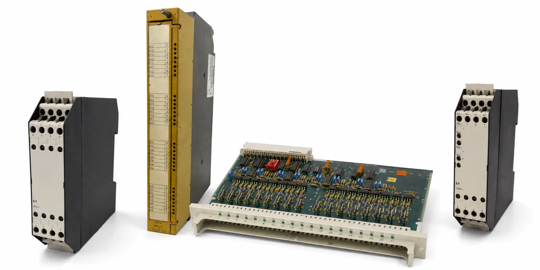
Siemens SIMATIC S5 digital input modules transfer on/off signals from pushbuttons, limit switches, relay contacts and suitable sensors to the PLC program. This category contains DC inputs, AC inputs, logic-level boards, process interrupt models and special F/Ex modules from different S5 families. An input module reads field signals; it does not control a load like an output module.
Select the hardware using the complete 6ES5 order number, channel count, signal voltage, input current, isolation and CPU/rack compatibility. Different suffixes within a family may change common connections, delay, permitted signal types or auxiliary terminals.
PNP, NPN and common connections
A PNP sensor supplies a positive output signal; an NPN sensor switches its output towards M/0 V. Match this behaviour to the input circuit and common reference. Do not assume one PNP/NPN wiring arrangement for every S5 input; check current direction and the manufacturer’s connection diagram.
Dry contacts, two-wire sensors and three-wire sensors require different checks. A dry contact switches an appropriate field supply. Electronic sensors also require attention to operating current, off-state leakage and voltage drop. Galvanic isolation does not necessarily isolate every channel from every other channel; inspect common terminals and isolation groups separately.
420, 421 and 422 compact 24 V DC inputs
6ES5 420-8MA11 provides 4 × 24 V DC, 6ES5 421-8MA12 provides 8 × 24 V DC, and 6ES5 422-8MA11 provides 16 × 24 V DC inputs. Check addressing and connections before selecting a module with a different channel count as a replacement.
Another 421 entry in this category is 6ES5 421-8MA11. Verify the label and revision of this legacy code separately; it must not automatically be treated as identical to 421-8MA12.
430 and 431 compact DC/AC inputs
6ES5 430-8MB11 has 4 × 24–60 V DC inputs, 6ES5 430-8MC11 has 4 × 115 V AC inputs, and 6ES5 430-8MD11 has 4 × 230 V AC inputs. The 430 prefix does not identify a single input voltage.
6ES5 431-8MA11 has 8 × 24 V DC inputs, 6ES5 431-8MC11 has 8 × 115 V AC inputs, and 6ES5 431-8MD11 has 8 × 230 V AC inputs. Verify permitted AC/DC operation, thresholds and common connections in the exact model’s documentation.
420 rack-mounted digital input boards
420-3BA / 4UA: 6ES5 420-3BA11 · 6ES5 420-4UA11 · 6ES5 420-4UA12 · 6ES5 420-4UA13 · 6ES5 420-4UA14. 420-5AA / 7LA: 6ES5 420-5AA11 · 6ES5 420-7LA11.
This group contains rack-mounted input boards. Check the front connector, signal common and any enable connection together. Selection using the 420 number alone can confuse compact and rack-mounted hardware.
430 rack-mounted input models
430-2BA / 3BA / 4UA: 6ES5 430-2BA11 · 6ES5 430-3BA11 · 6ES5 430-4UA11 · 6ES5 430-4UA12 · 6ES5 430-4UA13 · 6ES5 430-4UA14.
430-6AA / 7LA: 6ES5 430-6AA11 · 6ES5 430-7LA11 · 6ES5 430-7LA12 · 6ES5 430-7LA12-Z. For orders containing -Z, retain any additional option definition and the device label. Do not assume that the basic code establishes every characteristic.
431 rack-mounted and extended-voltage inputs
6ES5 431-3BA11 · 6ES5 431-4UA12 · 6ES5 431-6AA11 · 6ES5 431-7LA11. For example, 431-4UA12 has 16 inputs rated 24–60 V DC. Do not transfer those specifications directly to 431-7LA11 or other suffixes; distinguish DC and AC/UC input options.
432 family and process interrupts
6ES5 432-3BA12 · 6ES5 432-4UA11 · 6ES5 432-4UA12 · 6ES5 432-6AA12 · 6ES5 432-7LA11. 432-4UA12 has 32 × 24 V DC inputs and can generate a process interrupt with an appropriate configuration. Edge selection, interrupt enabling and CPU program handling must be configured together. This function should not be assumed identical across every 432 model.
433 logic-level and extended DC inputs
6ES5 433-8MA11 provides 8 × 5–24 V DC inputs. Another 433 board is 6ES5 433-7LA11. When connecting logic-level equipment, assess logic-0/logic-1 thresholds and input current as well as the nominal voltage.
434 logic-level and interrupt input models
434-4UA: 6ES5 434-4UA11 · 6ES5 434-4UA12. 434-7LA: 6ES5 434-7LA11 · 6ES5 434-7LA12.
434-4UA12 provides 32 channels with TTL/CMOS and suitably configured NAMUR connection options. NAMUR compatibility does not make this board intrinsically safe Ex equipment. 434-7LA12 is a different model with 8 × 24 V DC inputs and a process interrupt function.
435 and 436 AC/UC input boards
435 models: 6ES5 435-4UA12 · 6ES5 435-7LA11 · 6ES5 435-7LB11 · 6ES5 435-7LC11. A 24–60 V AC input board such as 435-4UA12 belongs to a different voltage group from 115 V-class 435-7L models.
436-4U / 6AA: 6ES5 436-4UA11 · 6ES5 436-4UA12 · 6ES5 436-4UB12 · 6ES5 436-6AA11. 436-7L: 6ES5 436-7LA11 · 6ES5 436-7LB11 · 6ES5 436-7LC11.
For example, 436-7LC11 has 8 × 230 V UC inputs. For UC operation, obtain the permitted AC/DC ranges from its technical specifications. Do not assume matching connector assignments where channel counts and common groups differ.
400, 401 and 405 legacy S5 input hardware
400 / 401: 6ES5 400-7AA13 · 6ES5 401-7AA13. 405: 6ES5 405-7AB11 · 6ES5 405-7AB21.
Select a spare for an older system using the complete code and host controller. Check board dimensions, edge connector, input voltage and any group signalling connections. Physical resemblance to a newer S5 board does not establish direct compatibility.
431-8FA11: special input module for the S5-95F
6ES5 431-8FA11 is special digital input hardware for the S5-95F system. For safety-related tasks, the manufacturer requires a redundant module pair across subunits A and B with appropriate parameter settings. Operation of one board alone does not validate the system’s safety function.
437-8EA12: four-channel NAMUR Ex input
6ES5 437-8EA12 is a four-channel intrinsically safe NAMUR input module. Its technical specifications state a typical input voltage of 8.2 V; sensor states are evaluated through current changes. It must not be wired as a standard 24 V PNP/NPN sensor input. Match the Ex bus unit, field device and circuit conditions using its manual.
Input delay and short pulses
Input delay and PLC cycle time are different. Electrical filtering affects signal acceptance at the module; the program cycle and process image affect when the information is processed. Pulses shorter than the filter interval or missed by program sampling can be lost. A standard digital input module should not be treated as a high-speed counter.
Contact bounce, interference or two-wire sensor leakage can make an input appear unstable. Do not simply conceal the problem with a software delay. Check the field signal, common reference, wiring and input thresholds together.
Addressing and field checks
Addressing example: a 16-input module starting at byte 4 and using two consecutive bytes is expressed as I 4.0–I 5.7 in English STEP 5 notation. The actual start address depends on the CPU, slot, switch settings and module arrangement; slot numbers are not universally input byte addresses across S5 systems.
A useful checking sequence is field voltage → channel LED → PLC input bit → program condition. A whole missing group may indicate a common connection, field supply or enable problem. For a single channel, distinguish the sensor, cable, terminal and input circuit.
Used equipment purchasing and selling
For a quotation, provide the complete model, quantity, working or faulty condition, label photograph and asking price. Send details of equipment you wish to sell to otomasyonavm@gmail.com. Sales require an invoice; used equipment is sold without returns. Workshop testing with a suitable system and controlled test signals may be arranged.
Editor's Note
Before applying a test signal, identify the labelled voltage and common terminal. A 24 V DC board, a 115 V AC board and a logic-level board can look similar while requiring very different signals.
A sensor LED alone does not establish a faulty PLC input. Measure the signal at the module terminal against the correct common reference. A broken cable, loose terminal or missing common can prevent a healthy sensor from being read.
When a whole group of inputs is missing, check the common connection, field supply and any enable terminals first. These checks often resolve the issue before a board replacement is needed.
A missed short pulse does not immediately prove a fault. Assess sensor pulse duration, input filtering and the PLC cycle together. A standard digital input cannot be expected to provide encoder or high-speed counter performance.
Do not assess a spare using just one channel. Test all required channels in both states and check any interrupt function. Record address switches, jumpers and connector wiring before removal, so incorrect settings do not make a sound replacement appear faulty.
OtomasyonAVM Resources and PDF Manuals
For system selection, review the SIMATIC S5 CPU families and S5 module categories. Check that the manual covers the complete order number and relevant hardware revision.
+ Shared Siemens SIMATIC S5 PDF archive
+ S5-100U Ex I/O manual — English
+ S5-115U system manual — English
+ S5-135U/155U system manual — English
Related Topics
S5 digital output modules · S5 digital input/output modules · S5 power supplies · S5 cables and connectors · S5 interface modules
Browse SIMATIC S5
Parent S5 module category · SIMATIC S5 CPU options · Siemens S5 PLCs · Used Siemens automation equipment
Siemens and External References
+ Siemens — S5-100U System Manual (English)
+ Siemens — S5-115U System Manual (English)
+ Siemens — S5-135U/155U System Manual (English)