
Temperature sensors accessories
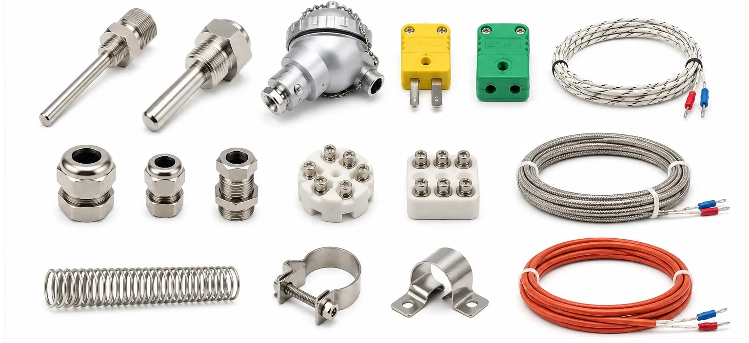
Temperature sensor accessories are the mechanical and electrical parts that allow a sensor to measure the process it was selected for. A good sensor can still produce a poor result if it is installed in the wrong thermowell, extended with the wrong cable, mounted with insufficient immersion, exposed to excessive vibration, or connected to an incompatible input.
In simple terms: selecting the sensor is only half of the measurement job. The probe still has to be positioned correctly, protected from the process, connected with the right materials and interfaced with electronics that understand its signal.
This is why accessories should be selected from the sensor technology, process temperature, pressure, flow, chemical environment, vibration, response-time requirement and electrical interface rather than from probe diameter or connector shape alone. If the sensing technology itself is not yet clear, start with What Is a Temperature Sensor?.
What actually counts as a temperature sensor accessory?
In an industrial measurement loop, an accessory may be mechanical, electrical or both. Common examples include:
thermowells and protective sheaths
connection heads and terminal blocks
bayonet caps and spring-loaded mounts
compression fittings, threaded adapters and flanges
thermocouple extension or compensating cable
thermocouple connectors
high-temperature lead wire
sealing and insulation materials
temperature transmitters and signal conditioners
Not every item belongs with every sensor. A thermocouple, Pt100 RTD, NTC thermistor and switching PTC thermistor have different electrical interfaces even when the finished probes look similar.
Mechanical accessory or measurement component?
A useful distinction is to ask what the component actually does. A thermowell protects and positions the probe. A connector joins conductors. A transmitter processes the raw sensor signal. A controller compares the measured value with a setpoint. These functions can exist in the same assembly, but they should not be treated as the same device.
What does a thermowell or protective sheath do?
Directly exposing a temperature element to a process is not always practical. Pressure, velocity, abrasion, corrosive fluids or mechanical impact may damage a probe. A thermowell provides a pressure-retaining mechanical barrier between the sensor and the process in applications where that construction is appropriate.
A removable sensor can then be inserted into the thermowell, allowing some installations to service or replace the sensing element without opening the process boundary.
The protection is not free: additional metal introduces thermal mass and thermal resistance. A heavy thermowell can substantially slow the response compared with a small directly immersed probe.
Why are insertion length and fit important?
A temperature probe should measure the process—not the fitting, vessel wall or surrounding air. Insufficient immersion can create stem-conduction error, especially where the process temperature differs greatly from ambient temperature.
The fit between probe and thermowell also matters. Excessive air gap can increase thermal lag. The correct dimensions depend on the probe, thermowell geometry and process conditions; a “tight fit” should never be improvised in a way that prevents safe removal or violates the manufacturer's design.
Thermowells in flowing and pressurized processes
In a pipe, the thermowell is a mechanical component exposed to process pressure and flow-induced forces. Material, insertion length, diameter, mounting method and process velocity all matter. High-flow service should therefore be treated as a mechanical design problem as well as a temperature-measurement problem.
For steam and hot-oil systems, temperature measurement may also need to be considered together with the separate process variable of steam and hot-oil pressure. A temperature probe does not replace pressure protection or pressure measurement.
Bayonet caps, springs and adjustable mounting
Spring-loaded bayonet assemblies are common on plastics machinery, moulds, heated machine parts and similar applications where the sensing tip must remain in contact with a defined measuring point.
The spring is not merely a convenience. It can help maintain contact as the machine vibrates or dimensions change slightly with temperature. Incorrect spring force, the wrong adapter or a poorly positioned sensing tip can instead create wear, sensor damage or a reading that does not represent the intended surface.
The mechanical principle can be used with different sensing technologies. For example, bayonet Pt100 probes and thermocouple bayonet probes can share a similar mounting concept while requiring completely different input electronics.
J-type and K-type bayonet accessories are not automatically interchangeable
Mechanical dimensions may look identical, yet the thermoelectric materials must still match the thermocouple type. Before reusing a cable, connector or extension lead, confirm whether the installed sensor is Type J or Type K.
Why is thermocouple cable different from ordinary electrical wire?
A thermocouple produces a very small thermoelectric EMF. The underlying physics is the Seebeck effect, so conductor material is part of the measurement system.
For this reason, extending a thermocouple with arbitrary copper cable is not equivalent to extending an ordinary voltage-output sensor. The circuit should use extension or compensating cable appropriate to the thermocouple type and the intended temperature region.
The current industrial cable framework is explained under IEC 60584-3 thermocouple extension and compensating cables.
Extension cable vs compensating cable
These terms should not be used as synonyms. An extension cable uses conductors intended to reproduce the thermoelectric behaviour of the corresponding thermocouple over its specified extension-wire range. A compensating cable uses alternative alloys whose behaviour is designed to approximate the required thermocouple EMF over a more limited range.
The practical distinction is covered in Difference Between Thermocouple Extension and Compensating Cables.
Can copper be used anywhere in a thermocouple system?
Eventually the thermocouple circuit normally transitions to copper inside the measuring instrument. The important question is where that transition occurs and whether the instrument measures the temperature of that reference region correctly.
Introducing copper connections at uncontrolled temperatures can move the effective reference junction and create error. This is why thermocouple-compatible cable and connector materials are important before the intended copper transition at the instrument.
Cold-junction compensation is part of the connection system
A thermocouple does not directly produce “absolute temperature.” The measured EMF depends on both the measuring region and the reference connection region. Modern instruments therefore use cold-junction compensation (CJC).
The “cold” junction does not need to be physically cold. The important requirement is that the instrument knows the temperature of the thermocouple-to-copper transition region accurately enough to perform the correct EMF-domain compensation.
A badly designed terminal arrangement can create temperature gradients across the connection block. In that case the CJC sensor may not represent both transition points accurately. Good terminal layout therefore matters even when the thermocouple probe itself is perfect.
Thermocouple connectors and polarity
Thermocouple plugs and sockets should use contact materials compatible with the thermocouple system. Mechanical fit alone does not prove electrical compatibility.
Polarity must also be preserved. Reversing the positive and negative conductors reverses the thermoelectric EMF and can create severe measurement error.
Wire colours are not universal across every standard, so type markings and connector identification should be checked instead of assuming that one colour convention applies everywhere.
Do grounded and ungrounded junctions change accessory selection?
Yes. In a metal-sheathed thermocouple, the measuring junction may be electrically bonded to the sheath, electrically isolated from it, or exposed directly to the process.
A grounded junction can provide fast thermal coupling in an otherwise equivalent construction, while an ungrounded junction provides electrical isolation from the sheath. An exposed junction can respond very quickly but has less mechanical and chemical protection.
“Grounded” in this context does not mean protective earth. It describes the electrical relationship between the measuring junction and the metal sheath. The full comparison is available in Grounded, Ungrounded and Exposed Junction Thermocouples.
Mineral-insulated metal-sheathed thermocouples
In MIMS / MI construction, thermoelements run inside a metal sheath and are separated by compacted mineral insulation. This is not merely “a protective tube around a normal wire”; it is an integrated thermocouple cable/probe construction.
Base-metal Type T, J, E, K and N MIMS constructions are covered by IEC 61515 mineral-insulated metal-sheathed thermocouples.
Pt100 and Pt1000 accessories use a different electrical logic
A platinum RTD measures resistance rather than thermoelectric EMF. That difference changes the wiring accessories completely. Thermocouple compensating cable should not be used as though it were a special Pt100 cable.
For a standard Pt100, ordinary suitable copper conductors can be used, but lead resistance becomes part of the measurement in a 2-wire connection.
2-wire: simplest wiring; lead resistance adds directly to measured resistance.
3-wire: compatible electronics can compensate much of the lead resistance when conductor resistances are sufficiently matched.
4-wire: separate current and voltage paths provide the best rejection of lead resistance.
For long cable runs, Pt1000 can also be worth comparing because its higher nominal resistance reduces the relative effect of the same lead resistance. It is not, however, automatically more accurate or suitable for a higher process temperature.
RTD connection heads and terminal blocks
A connection head provides mechanical protection for terminals and may provide space for a head-mounted transmitter. The internal terminal arrangement must match the actual 2-, 3- or 4-wire probe.
A four-terminal head does not automatically mean the installed element is a four-wire Pt100; the actual sensor wiring must be traced and confirmed.
If you are still deciding between RTD and thermocouple construction, use the detailed Thermocouple vs Pt100 comparison rather than selecting from connector style.
NTC and PTC probes: encapsulation is part of the measurement
Thermistors are often embedded in cable probes, metal capsules or molded assemblies. Encapsulation protects the element, but it also changes thermal response.
For an NTC, the electrical identity is not simply “10K.” The R25 value, Beta characteristic and R/T curve must match the electronics.
A switching PTC used for motor protection serves a different purpose. It is often selected around a sensing or switching temperature so a protection circuit can detect an over-temperature condition.
A stainless-steel probe body does not automatically make an NTC or PTC assembly waterproof, chemically resistant or suitable for immersion. Cable entry, potting compound, seal design and the actual medium must also be considered.
High-temperature cable: what should actually be specified?
“High-temperature cable” is too vague for engineering selection. Cable insulation may use silicone, PTFE, fiberglass or other constructions, each with different continuous-temperature, abrasion, moisture and chemical-performance limits.
The process can be at 800 °C while the cable exits through a region that remains far cooler. Conversely, a sensor may measure a moderate process while the cable is routed next to heaters or hot metal. Sensor measuring range and cable exposure temperature are separate specifications.
Is silicone automatically suitable for every hot application?
No. Silicone cable, sealant and potting materials exist in many formulations. Temperature rating, oil resistance, chemical resistance, curing method and long-term thermal ageing must be checked for the specific material.
When is a temperature transmitter useful?
A temperature transmitter or sensor converter is useful when the raw sensor cannot or should not be carried directly to the control system.
Typical reasons include:
long cable distance
PLC without the required RTD or thermocouple input
need for galvanic isolation
electrically noisy environment
requirement for a standardized process signal
Depending on the device, the transmitter can convert sensor information into 4–20 mA or 0–10 V, or provide a digital communication interface.
A transmitter should not be described as another sensing technology. It is an electronic interface in the measurement chain. Its own input error, CJC or RTD excitation behaviour, output accuracy and power requirements become part of the total measurement system.
Can a sensor be connected directly to a PLC?
Only if the input hardware supports that sensor. A thermocouple input, RTD input, thermistor input and standard voltage/current input are different circuits.
If the signal has already been converted to a standard process range, the PLC side is explained in What Are Analog Inputs and Outputs?. For the controller itself, see What Is a PLC?.
A temperature controller is not a sensor accessory
A sensor measures. A transmitter converts. A temperature controller compares the measured value with a setpoint and decides what the process should do next.
In a heating loop, the controller may drive an SSR or contactor. If proportional closed-loop control is required, the control principle can be studied separately in What Is PID Control?.
Noise, shielding and cable routing
Low-level sensor wiring should not be routed carelessly beside high-current motor and switching conductors. This is especially important for thermocouples because the useful signal is only in the millivolt range.
Machines containing VFDs, servo drives, contactors and high-power heaters can produce common-mode and differential electrical interference. Good practice may involve physical separation, appropriate twisted/shielded cable, correct shield termination and avoiding unnecessary ground loops.
There is no universal rule that “both ends of every shield must be grounded” or “one end must always be left open.” Shield and grounding practice depends on the instrument input, plant grounding system, cable construction and frequency of the interference. Follow the equipment manufacturer's installation guidance.
Ground loops and grounded thermocouple junctions
A grounded thermocouple junction may electrically connect the measurement circuit to the process through the sheath. That can be useful in one installation and troublesome in another. Isolation strategy should therefore be decided at system level rather than by automatically choosing a grounded probe because it responds faster.
Can accessories improve sensor accuracy?
Correct accessories can reduce installation error, but they do not magically improve the intrinsic tolerance of the sensing element.
A correctly selected extension cable can prevent avoidable thermocouple error. A 4-wire RTD connection can reject lead resistance. A properly sized thermowell can protect the probe without creating unnecessary thermal lag. These are improvements to the measurement system, not changes to the fundamental sensor class.
For thermocouple systems in particular, sensor tolerance is only one contributor. The distinction is discussed in How Is Measurement Uncertainty in a Thermocouple System Calculated?.
Common accessory-selection mistakes
Using ordinary copper cable to extend a thermocouple at an uncontrolled transition temperature.
Selecting a connector because it physically fits while ignoring thermocouple type and polarity.
Choosing a very heavy thermowell without considering response time.
Using too little insertion depth and measuring stem conduction instead of the process.
Assuming a stainless probe is automatically waterproof or chemically compatible.
Connecting a Pt100 to a thermocouple input or a thermocouple to an ordinary 0–10 V input.
Treating a transmitter as though it removes all sensor and installation uncertainty.
Routing low-level sensor wiring in the same path as VFD motor cables without considering EMI.
How should temperature sensor accessories be selected?
Start with the actual measurement task, not the accessory catalogue.
1. Identify the sensor technology.
Is it a thermocouple, Pt100/Pt1000, NTC, PTC or an active electronic sensor?
2. Define the process conditions.
Normal temperature, peak temperature, pressure, flow velocity, vibration, chemical exposure, cleaning method and mechanical load all matter.
3. Define the measuring point.
Liquid temperature, gas temperature, pipe-wall temperature, motor winding temperature and moving-product surface temperature require different installation methods.
4. Define the required response time.
A massive thermowell may be mechanically excellent but too slow for a fast control loop.
5. Define the electrical interface.
Confirm thermocouple type, RTD wiring, thermistor characteristic, input module and whether a local transmitter is required.
6. Define cable and environmental requirements.
Cable temperature, flexing, oil, moisture, abrasion, EMC environment and installation length should all be specified.
Application-based accessory selection
Plastic machinery / heated mould: spring-loaded bayonet construction can maintain contact; verify probe length, spring travel and sensor type.
Pressurized liquid or steam line: evaluate a properly engineered thermowell and process connection; temperature and pressure are separate design variables.
High-temperature furnace: compare thermocouple type, sheath material, mineral-insulated construction and cable exit temperature. For Type K fundamentals, see What Is a Type K Thermocouple?.
Long cable to PLC: compare native thermocouple/RTD wiring with a local transmitter and 4–20 mA signal. The lowest-cost sensor does not necessarily produce the lowest-cost installed system.
Motor winding protection: verify whether the motor requires continuous temperature measurement or a switching PTC protection chain. Do not replace one with the other simply because both are temperature-dependent resistors.
Moving or inaccessible target: a contact accessory may not solve the problem at all. In that case evaluate non-contact temperature measurement instead.
What should be specified when