
what is K-type (NiCr-Ni) thermocouple sensor?
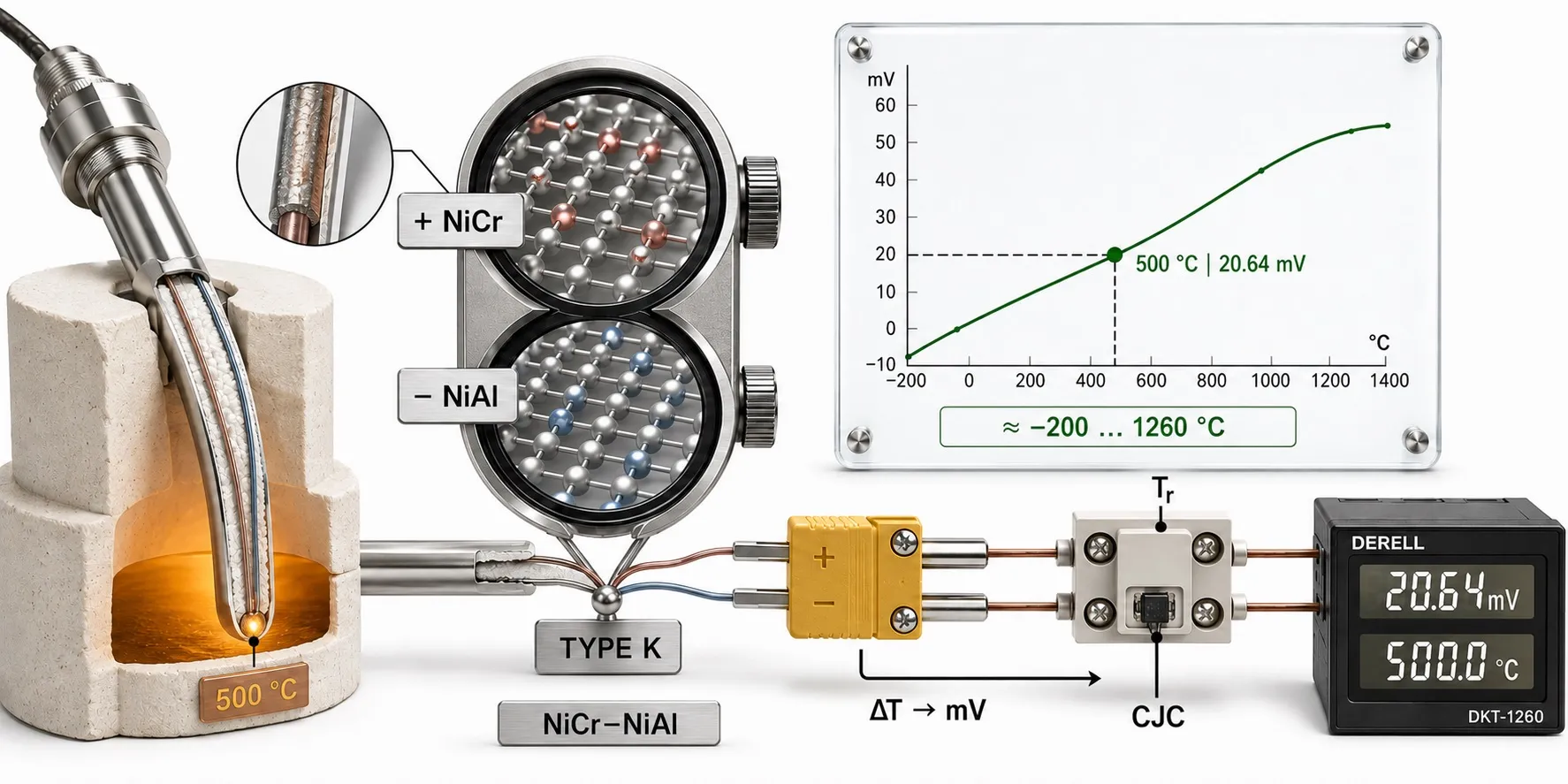
Type K is one of the most widely used industrial thermocouple types. It measures temperature through the thermoelectric EMF produced by two dissimilar thermoelements exposed to a temperature gradient.
The positive Type K thermoelement is a nickel-chromium alloy (NiCr), while the negative thermoelement is a nickel-aluminium-based alloy (NiAl). The traditional shorthand “NiCr–Ni” is still seen in product catalogues and older industrial documentation, but simply calling the negative leg “nickel” does not fully describe its alloy composition.
In simple terms: a Type K thermocouple does not generate a fixed number of millivolts per degree. It produces a small thermoelectric voltage determined by the temperature distribution along the two thermoelements. A thermocouple input combines that measured EMF with the temperature of the copper connection terminals and converts the result into process temperature.
The physical effect behind this measurement is explained in What Is the Seebeck Effect?.
Type K technical guide — quick navigation
How Type K works · Live Type K simulation · Temperature range · EMF / mV table · IEC tolerances · Cold-junction compensation · Extension cable · Grounded / ungrounded junction · Drift and errors · Selection guide
How does a Type K thermocouple work?
A Type K thermocouple uses two dissimilar thermoelectric alloys. The conductors are joined at the measuring end and connected to a thermocouple instrument at the other end.
A common simplified explanation says that “voltage is generated at the hot junction.” That is useful for an introduction, but physically incomplete.
The thermoelectric EMF develops along regions of the thermoelements that are exposed to temperature gradients. The complete circuit therefore responds to the temperature difference between the measuring region and the reference connection region.
Conceptually:
Emeasured = E(Thot) − E(Treference)
Thermocouple reference tables and standard functions normally express EMF relative to a 0 °C reference junction. A modern instrument therefore measures the real terminal temperature, compensates the EMF to the 0 °C reference condition and only then converts the resulting EMF to temperature.
For the complete principle, see What Is a Thermocouple?.
How is Type K actually measured? NIST ITS-90 simulation
• Type K is not treated as a fixed 41 µV/°C sensor; the NIST ITS-90 Type K reference function is used.
• The raw thermocouple signal reaching the instrument is approximately E(hot) − E(terminal).
• During CJC, the instrument adds the terminal temperature's equivalent Type K EMF—not simply its temperature in degrees.
• The resulting 0 °C-referenced EMF is then converted back into temperature.
• Change the terminal temperature: the raw mV changes, while correct CJC keeps the displayed process temperature approximately unchanged.
• Increase electrical noise to see why low-level thermocouple wiring requires careful installation.
Training note: this is an educational simulation. It does not model every uncertainty contributor of a real Type K installation, including thermocouple tolerance, extension-wire tolerance, CJC sensor error, drift, inhomogeneity, immersion error or calibration uncertainty.
What is the temperature range of a Type K thermocouple?
There is no single temperature limit that applies to every Type K probe.
The NIST ITS-90 Type K reference function extends approximately from −270 °C to +1372 °C.
IEC 60584-1:2013 also specifies the Type K reference relationship, but the IEC polynomial range for Type K is restricted to 1300 °C.
These are reference-function limits, not guaranteed continuous operating limits for a physical probe.
The real service limit depends on:
thermoelement diameter
probe diameter
sheath material
mineral insulation
atmosphere
oxidation
vibration
thermowell
extension cable and connector construction
A small flexible cable probe may therefore have a far lower safe temperature than a correctly designed mineral-insulated metal-sheathed probe, even though both contain Type K thermoelements.
Can Type K be used at cryogenic temperatures?
Reference data extend far below 0 °C, but that does not make Type K the preferred thermocouple for every cryogenic application.
At very low temperatures its Seebeck coefficient decreases, which reduces electrical sensitivity. For low-temperature work, Type E or Type T may be worth comparing depending on the process and instrumentation.
How many millivolts does a Type K thermocouple produce?
The Type K Seebeck coefficient is not constant.
The often-quoted value of approximately 41 µV/°C is a useful engineering approximation around some temperature regions, but it should not be applied as a linear conversion across the whole Type K range.
With the reference junction at 0 °C, typical Type K reference values are:
| Temperature | Type K EMF |
| −200 °C | −5.891 mV |
| −100 °C | −3.554 mV |
| 0 °C | 0.000 mV |
| 100 °C | 4.096 mV |
| 200 °C | 8.138 mV |
| 500 °C | 20.644 mV |
| 800 °C | 33.275 mV |
| 1000 °C | 41.276 mV |
| 1200 °C | 48.838 mV |
For the full relationship between standard thermocouple tables, ITS-90 and polynomial functions, continue to Thermocouple Reference Tables, Polynomials and ITS-90.
What are the IEC tolerance classes for Type K?
A Type K thermocouple does not have one fixed accuracy such as “±1 °C.”
IEC 60584-1 defines temperature-dependent manufacturing tolerances.
| Class | Validity range | Tolerance |
| Class 1 | −40…+1000 °C | ±1.5 °C or ±0.004×|t|, whichever is greater |
| Class 2 | −40…+1200 °C | ±2.5 °C or ±0.0075×|t|, whichever is greater |
| Class 3 | −200…+40 °C | ±2.5 °C or ±0.015×|t|, whichever is greater |
These values describe thermocouple manufacturing tolerance. They are not the total installed-system measurement uncertainty.
The complete measurement also includes contributions from the instrument input, CJC, extension cable, drift, thermal gradients and installation.
For that distinction, see How Is Measurement Uncertainty in a Thermocouple System Calculated?.
Why does a Type K thermocouple need cold-junction compensation?
A thermocouple does not produce a voltage corresponding only to the hot-junction temperature.
The measured voltage reflects the difference between the measuring region and the reference connection region.
The instrument therefore measures the temperature where the thermocouple circuit transitions to the copper input terminals.
Conceptually:
E0°C reference = Emeasured + E(Tterminal)
The instrument then converts that compensated Type K EMF to temperature.
CJC is therefore not simply “adding the cold-junction temperature in degrees.”
The complete process is explained in What Is Thermocouple Cold-Junction Compensation?.
Does the cold junction have to be cold?
No. “Cold junction” is historical terminology.
A modern thermocouple terminal block can be at 20 °C, 30 °C or another temperature. What matters is that the CJC sensor accurately represents the temperature of the actual thermocouple-to-copper transition points.
If one side of the input terminal block is significantly warmer than the other, a single CJC sensor may not represent both connections accurately. Good thermocouple inputs therefore try to maintain an approximately isothermal terminal region.
How should a Type K thermocouple cable be extended?
A Type K circuit should not normally be extended arbitrarily with ordinary copper cable.
The thermoelectric circuit should be continued with appropriate IEC 60584-3 extension or compensating cable.
Extension and compensating cables are not identical products. Their differences are explained in Difference Between Thermocouple Extension and Compensating Cables.
What happens if copper cable is inserted into the thermocouple circuit?
Each transition from thermocouple alloy to copper creates additional dissimilar-metal junctions.
If paired transition junctions are at exactly the same temperature, their effects can largely cancel. If the two junctions experience different temperatures, additional thermoelectric EMF can appear and create a measurement error.
The most reliable approach is therefore to carry the correct Type K thermoelectric circuit to the instrument's intended thermocouple terminal region.
Can Type K polarity be identified by wire colour?
Wire colours depend on the standard being used. IEC, ANSI and other identification systems do not necessarily use the same colours.
Do not identify polarity from colour alone unless the applicable cable standard is known. Check the Type K marking, connector polarity and manufacturer documentation.
Grounded, ungrounded and exposed-junction Type K probes
Metal-sheathed Type K probes are commonly manufactured using three different measuring-junction constructions.
Grounded junction: the measuring junction is electrically bonded to the metal sheath. For otherwise similar construction this can provide fast thermal coupling, but there is no electrical isolation between junction and sheath.
Ungrounded junction: the measuring junction is electrically insulated from the metal sheath. This can be useful where ground loops, different electrical potentials or electrical noise are important.
Exposed junction: the thermocouple junction is directly exposed to the process. Response can be very fast, but mechanical and chemical protection are reduced.
In this context, grounded does not mean protective earth. It describes the electrical connection between the measuring junction and the probe sheath.
See Grounded, Ungrounded and Exposed Junction Thermocouple Differences for the full comparison.
What is a mineral-insulated Type K thermocouple?
In MIMS / MI construction, the Type K thermoelements run through a metal sheath and are separated by densely compacted mineral insulation, commonly magnesium oxide.
This construction can provide:
small probe diameter
mechanical strength
high-temperature capability
bendable probe construction
good electrical insulation
The relevant industrial standard is discussed in IEC 61515 Mineral-Insulated Metal-Sheathed Thermocouples.
Why can a Type K thermocouple drift over time?
Electrical continuity does not prove that a thermocouple is still correctly calibrated.
Long-term thermal exposure can change the thermoelectric behaviour through:
oxidation
local alloy-composition changes
chemical contamination
mechanical strain
thermoelectric inhomogeneity
Type K is relatively resistant to oxidation compared with several other conventional base-metal thermocouples, which is one reason it is widely used above moderate temperatures.
However, its thermoelements can still oxidize and drift during prolonged elevated-temperature exposure.
In atmospheres with limited oxygen or reducing conditions, Type K can also suffer additional composition changes. Bare-wire use in hydrogen, carbon monoxide and similar reducing environments requires particular care.
What is “green rot” in Type K thermocouples?
“Green rot” is a historical term associated with selective chromium oxidation in the positive Type K thermoelement under certain low-oxygen / reducing high-temperature conditions.
The thermoelectric properties of the affected region change, causing calibration error. The risk depends strongly on temperature, oxygen availability, time and probe protection.
For long-term high-temperature applications where base-metal stability is especially important, compare Type K with Type N thermocouple.
Why does a Type K thermocouple show the wrong temperature?
Common causes include:
instrument configured for the wrong thermocouple type
reversed Type K polarity
wrong extension or compensating cable
CJC sensor or terminal-gradient error
dissimilar-metal connections at different temperatures
electrical noise from VFD or power cables
ground loops
insufficient probe immersion
heat conduction through the sheath or thermowell
high-temperature drift
chemical contamination
What happens if Type K polarity is reversed?
Reversing the positive and negative thermoelements reverses the sign of the thermoelectric EMF.
If the process is hotter than the terminal region, the instrument may indicate an unexpectedly low temperature, a negative deviation or an input error.
Always verify polarity from thermocouple markings and the applicable wiring standard rather than assuming colour conventions.
What happens if a thermocouple is shorted?
If the two thermocouple conductors contact one another before the intended measuring junction, a new effective junction can be created at the short-circuit point.
The instrument may then indicate a temperature related to the location of that accidental junction instead of the intended process temperature.
Unlike an open-circuit thermocouple, this fault may not always trigger an obvious “sensor break” alarm.
Can a Type K thermocouple connect directly to a PLC?