
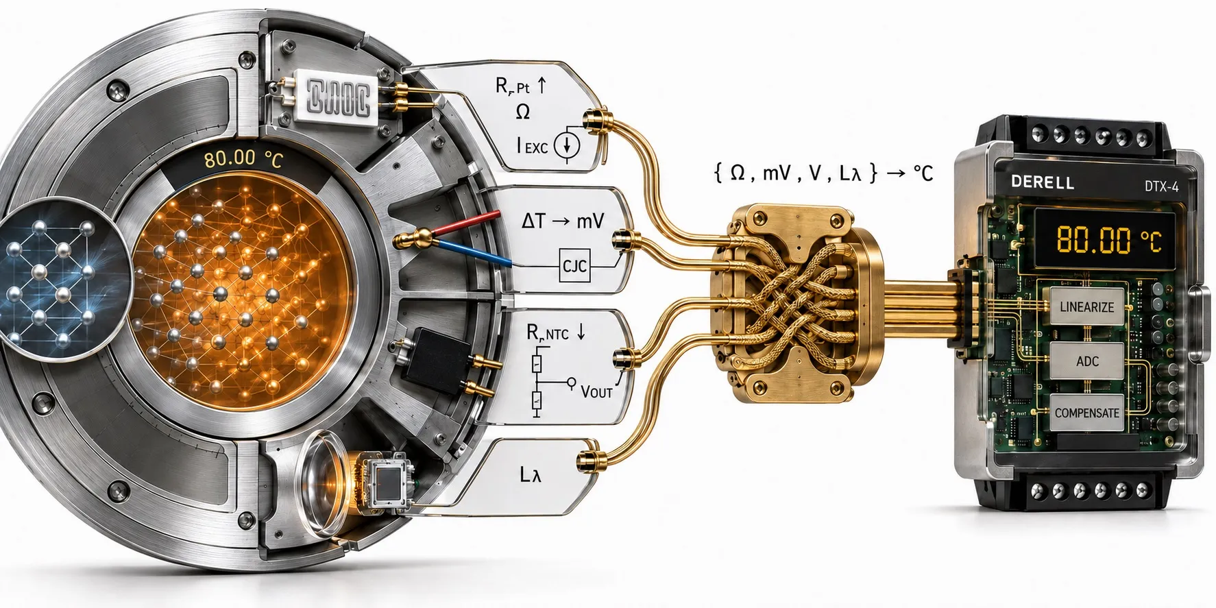
Temperature is not the same thing as heat
Temperature describes a thermal state; heat is energy transferred because of a temperature difference. Temperature is expressed in kelvin or degrees Celsius. Transferred energy is expressed in joules, while the rate of heat transfer can be expressed in watts. A probe reading 80 °C does not, by itself, tell you how much energy a process has delivered.
Consider a water-heating loop. To estimate the heat carried by the water, you need more than the outlet temperature: the inlet temperature, flow rate and fluid properties also matter. A temperature probe, a heat-flow sensor and a complete heat meter therefore solve different measurement problems. Define the quantity and measurement location before selecting the hardware.
Temperature sensor types: compare the principle, not the shape
The table separates the sensing principle from the electronics needed to read it. It is not a universal accuracy ranking or an operating-temperature guarantee. A thin probe, a threaded sensor and a terminal-head assembly can contain different sensing elements despite looking similar.
| Sensor family | What is measured electrically or optically? | What must the system provide? |
|---|---|---|
| Thermocouple | Thermoelectric EMF, usually measured in microvolts or millivolts. | Correct thermocouple type, reference-junction treatment and low-level input electronics. |
| Platinum RTD | Temperature-dependent resistance; Pt100 and Pt1000 are familiar examples. | Compatible resistance input, appropriate excitation and lead-resistance management. |
| NTC thermistor | Nonlinear resistance that decreases with temperature. | The correct nominal resistance, reference temperature and resistance–temperature curve. |
| PTC thermistor | Resistance that rises over the relevant region; switching types rise sharply near a threshold. | Whether the task is continuous measurement or over-temperature detection. |
| Integrated semiconductor sensor | An on-chip temperature response converted into an analog or digital output. | Supply voltage, interface and thermal coupling to the point being monitored. |
| Infrared sensor or pyrometer | Radiation arriving from a target is detected and interpreted optically. | Emissivity, spectral band, target size, optical path and detector compensation. |
Thermocouples: a voltage measurement, not a resistance measurement
A thermocouple joins two materials with different thermoelectric properties. Its useful signal comes from the Seebeck effect along portions of the conductors exposed to temperature gradients. The welded junction makes the electrical connection; it should not be treated as an isolated voltage generator independent of the rest of the circuit.
For example, Type K uses nickel-chromium and nickel-aluminium-based thermoelements. Different thermocouple types have different temperature–EMF relationships. The input must use the correct reference function, such as the relevant function covered by IEC 60584-1. A Type K sensor and a Type J input setting are not a valid match.
The instrument also needs the reference-junction temperature. Electronic cold-junction compensation accounts for the thermocouple-to-copper transition region before the EMF is converted into temperature. Correct extension or compensating cable preserves the intended measurement circuit. The sensor generates its own EMF, but the instrument reading it normally still needs power.
Pt100 and Pt1000: temperature from platinum resistance
A platinum RTD uses the predictable change in platinum resistance. Pt100 is nominally 100 Ω at 0 °C; Pt1000 is nominally 1000 Ω at 0 °C. “Pt” identifies platinum. The tenfold resistance difference does not make Pt1000 automatically ten times more accurate or suitable for a higher process temperature.
The measuring circuit applies a small excitation and determines resistance. Element construction, tolerance, lead configuration and mechanical protection all affect the result. IEC 60751 defines the industrial platinum resistance relationship and related requirements; the finished probe’s service limit must still come from its specification. Use the RTD-versus-thermocouple comparison when choosing between stable resistance measurement and a wider-temperature thermoelectric solution.
NTC thermistors: high sensitivity with a specific resistance curve
An NTC thermistor decreases in resistance as it becomes warmer. “10K NTC” usually identifies 10 kΩ at 25 °C, not a complete sensor specification. R25, Beta value and the actual resistance–temperature curve must match the electronics. Two 10K devices can agree near the reference point and disagree elsewhere. Resistance tolerance is not the same as a percentage temperature-accuracy guarantee.
Small thermistors can be useful in electronics, refrigeration and compact probes. Their response depends on the package and thermal contact, not merely the nominal resistance. A temperature-sensing NTC is also not interchangeable with a power NTC designed to heat itself while limiting inrush current.
PTC thermistors: identify the intended function
PTC means positive temperature coefficient. In a switching ceramic PTC, resistance increases sharply around a characteristic temperature region. This is useful for detecting a thermal limit rather than displaying a precise continuous temperature. The PTC protection principle requires a suitable sensing circuit or protection input; the thermistor does not cool the motor itself.
Not every PTC has the same switching curve or purpose. PTC devices may also be designed for current protection or self-regulating heating. Select the part by its electrical and thermal specification, not by the letters PTC alone.
Infrared sensors and thermopiles: two levels of the same explanation
An infrared thermometer or pyrometer interprets thermal radiation without touching the target. For a target that is opaque in the measurement band, the result relates primarily to the observed surface, not automatically to the material’s core temperature. Emissivity, field of view and the optical path are therefore part of the measurement, not optional setup details. Infrared measurement is not limited to visibly glowing objects.
A laser spot usually helps with aiming; it is not the temperature-sensing beam. The target must fill the specified measurement spot. Shiny metal, glass and thin plastic may require particular spectral bands or other precautions. A window that passes visible light does not necessarily pass the infrared wavelengths used by the instrument.
A thermopile is a detector structure, commonly made from multiple thermocouples connected electrically in series. Absorbed radiation warms its active junctions relative to a reference region, producing a Seebeck voltage. An infrared temperature sensor can therefore contain a thermopile. “Infrared” describes the radiation-measurement method; “thermopile” describes how a detector converts absorbed energy into an electrical signal. These are not mutually exclusive sensor families.
Integrated sensors, thermometers and temperature switches
An integrated semiconductor sensor combines a temperature-sensitive semiconductor structure with electronics. Depending on the device, the output may be analog or digital, for example I²C. A local sensor measures its own package or die temperature; correct mounting is needed for that reading to represent another component. A board-level digital interface should not be assumed to be an industrial fieldbus connection.
A thermometer is a measuring instrument, often combining a sensor and a display. A temperature switch or thermostat changes an output around a defined threshold. A switch contact does not necessarily provide a numerical temperature. Specify whether the application needs measurement, indication, routine control or an independent limit function.
From a sensor signal to a temperature value
A bare sensor and a temperature transmitter are different parts of the measurement chain. A temperature transmitter or sensor converter reads resistance or thermocouple EMF, applies the required conversion and supplies a usable output. Depending on the model, this might be 4–20 mA, 0–10 V or digital data. Adding electronics does not create a new underlying temperature-sensing principle.
For a worked example, assume a transmitter is configured linearly for 0–200 °C = 4–20 mA. In that configuration, 12 mA represents 100 °C. The 4–20 mA signal range describes how information is transported; it does not identify whether the original element was an RTD, thermocouple or another sensor. Both transmitter and receiving input must use the same scaling.
A PLC can use the resulting temperature for alarms, sequences or control. An operator display can show the value, while SCADA monitoring and logging can store trends and alarm history. These are downstream functions: a polished display cannot compensate for an unsuitable sensor or incorrect conversion.
Wiring and power: the connector does not identify the signal
A two-wire Pt100 is not a two-wire 4–20 mA transmitter. In the RTD circuit, lead resistance can add to the measurement. Three-wire compensation relies on the relevant lead resistances being suitably matched. Four-wire measurement separates excitation and voltage-sensing paths. In a loop-powered transmitter, the two wires instead carry both operating power and the current signal.
Check the input type and electrical limits before connecting anything. An RTD input, thermocouple input, thermistor input and ordinary voltage/current input are not interchangeable. Even “RTD supported” is insufficient without checking the accepted resistance values, characteristic and wiring configurations. Hardware, terminal wiring and software settings must agree.
A DIN-rail power supply may power a transmitter or controller, but 24 V must not be applied directly across a bare RTD, thermistor or thermocouple. Follow the specified excitation and supply connections. A sensor’s two leads are not automatically supply terminals.
How to choose a temperature sensor for the actual application
Start with the measurement point: bulk liquid, pipe surface, furnace atmosphere, motor winding, circuit board or moving product. Then define normal and peak temperature, permissible error, response time, environment and existing input hardware. The following are engineering starting points, not approval of an unspecified product.
Stable liquid or process measurement: investigate Pt100 RTDs with a suitable immersion probe. Where two-wire lead resistance is significant, compare Pt1000 or a different wiring architecture. Check sensor class and input support before assuming that a higher resistance will solve the entire error budget.
Electronics, batteries and refrigeration: compare the required range with the NTC resistance curve and controller characteristic. Matching the connector or the “10K” label is not enough. An integrated local sensor is another option where an appropriate digital interface and thermal mounting are available.
Motor over-temperature detection: consider switching PTC behaviour and the compatible protection circuit. Where continuous numerical winding temperature is required, use the motor’s specified sensor and an input capable of reading that characteristic. Do not substitute one sensor technology just because it fits the same terminals.
Furnaces and hot gases: Type K and Type N are candidates to compare against the atmosphere, sheath and exposure time. Higher-temperature work may require a different alloy family, such as Type S or Type B. A reference-table limit is not the continuous service rating of an assembled probe.
Low-temperature or small, fast contact measurements: compare appropriately constructed RTDs and thermistors with Type T or Type E thermocouples. Check the complete probe’s response in the actual medium. The smallest bare element and the fastest finished assembly are not necessarily the same choice.
Moving, inaccessible or delicate targets: use the non-contact temperature measurement guide to evaluate material, surface finish, spot size and wavelength. Decide whether surface temperature is actually the quantity needed; infrared measurement does not automatically answer an internal-temperature question.
Long, electrically noisy signal runs: compare a suitable local transmitter and 4–20 mA transmission with direct sensor wiring. A transmitter can simplify the long cable run, but it introduces its own specification, power requirement and uncertainty contribution. Evaluate the complete chain, not just the output format.
Temperature sensing alongside drives, pressure and other sensors
These examples illustrate how different measurements and actuators can share a machine without performing the same task. They are suggested system architectures, not claims about a particular installed machine.
Plastics-processing machine: thermocouples or RTDs may monitor barrel heating zones, while a controller adjusts heater power. A variable frequency drive can regulate a process motor, a servo system can control motion, and an inductive proximity sensor can detect a metal position target. Position feedback, motor protection and barrel-temperature control remain separate functions.
Steam or thermal-oil circuit: temperature monitoring may be paired with pressure measurement for steam and hot-oil service. Pressure control does not replace temperature monitoring, and a normal temperature reading alone does not prove that flow is adequate. Select the additional measurements and interlocks from the process requirements.
HVAC or drying equipment: humidity control and temperature control address different quantities. Airflow is a further variable. A calorimetric flow sensor may use the cooling of a heated element and compensate for medium temperature, yet its principal output represents flow. Using a thermal sensing principle does not make every such device a temperature probe.
Why an apparently healthy sensor can give the wrong reading
The sensor may be measuring the wrong place. Insufficient immersion, poor surface contact, heat conducted through the mounting and an unsuitable protective pocket can make the sensing element differ from the intended process temperature. A sensor attached to a pipe wall does not automatically report the same temperature as the moving liquid inside it.
Electrical power can warm the sensor. RTDs and thermistors dissipate measurement power, P = IR. If heat removal is poor, self-heating makes the sensor warmer than its surroundings. The excitation, mounting and medium must therefore be considered together.
Display speed is not thermal response. Encapsulation, sheath mass and surrounding flow affect how quickly the element follows a temperature change. For an approximately first-order thermal response, one time constant corresponds to about 63.2% of a step change. A rapidly updating screen can still display a delayed measurement.
Wiring can corrupt an otherwise correct measurement. Common problems include wrong input selection, thermocouple polarity, inappropriate extension wire, unmatched RTD leads and interference coupled from power circuits. Follow the instrument’s shielding, isolation and cable-routing instructions. Software filtering is not a substitute for correcting a wiring fault.
A plausible number is not proof of a valid measurement. Open-circuit detection is valuable, but some faults are less obvious. A low-resistance short between thermocouple legs can shift the effective sensing location. Grounded, ungrounded and exposed-junction construction also changes the electrical relationship with the probe sheath. Inspect the complete circuit when diagnosing a suspicious reading.
Accuracy, resolution, tolerance and calibration
Resolution is the smallest displayed or distinguishable step; it is not the total measurement accuracy. A 0.1 °C display increment does not establish ±0.1 °C system performance. Sensor tolerance, conversion electronics, reference conditions, drift and installation all need consideration.
The relevant thermocouple reference functions and tolerances or platinum RTD specification describe only part of the job. The thermocouple measurement-uncertainty guide explains why sensor tolerance and the uncertainty of an installed system are different questions. Comparable discipline is needed for RTD, thermistor and optical measurements.
Calibration establishes the relationship between reference values and instrument indications under stated conditions. It is not automatically an adjustment. Record which probe, cable, transmitter and readout were included, together with the calibration points and uncertainty. Verification or recalibration needs should be assessed against the process requirements, service history and applicable procedures rather than an invented universal interval.
Routine control and over-temperature protection are different jobs
In a temperature loop, the measured value is compared with a setpoint. PID temperature control or suitable on/off logic then adjusts the actuator. An SSR is a power-switching device in that chain, not a temperature sensor. Sensor placement and response delay also affect how the controlled process behaves.
Where loss of control could create a hazardous temperature, do not assume that the normal control loop is sufficient protection. The application may require an independent limit device, defined sensor-failure behaviour and an appropriate shutdown path. A risk assessment must determine the protection architecture; adding a sensor or relay alone does not establish a verified safety function.
Specify the complete probe before comparing prices
“Bayonet,” “threaded,” “surface,” “immersion” and “terminal-head” describe construction or mounting, not the sensing principle. An identical-looking housing can contain an RTD, thermistor or thermocouple. Mineral-insulated metal-sheathed thermocouples are one specific construction, not a universal label for all metal probes.
For a useful quotation or replacement specification, state the medium, normal and peak temperature, sensor characteristic, permissible error, probe diameter, insertion length, fitting, cable, response requirement and receiving instrument. Include documentation or calibration needs where relevant. Compare sensor, wiring, input hardware and installation together rather than treating a bare element and a transmitter-equipped assembly as equivalent purchases.
The right temperature sensor is the one that fits the whole system
Begin with the quantity and location you need to measure. Then match the sensing principle, probe construction, wiring and input electronics. Thermocouple EMF, RTD resistance, thermistor curves and infrared radiation must not be treated as interchangeable outputs. A sound measurement becomes useful control information only when the installation and interpretation are equally sound.