
PID Control for Humidity
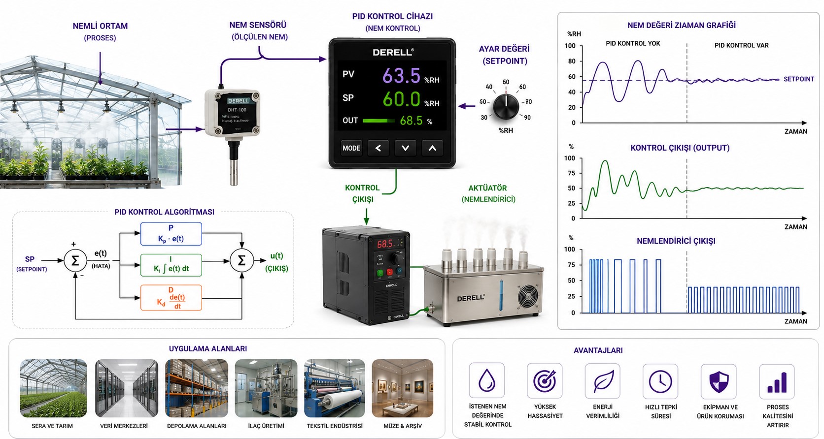
PID Control for Humidity: Relative Humidity Is Not Simply “How Much Water Is in the Air”
Humidity control is used in HVAC systems, laboratories, clean spaces, warehouses, electronics manufacturing, textile production, food processes and other applications where atmospheric moisture must remain within an acceptable range.
A simple humidification loop can be represented as:
Humidity setpoint → Humidity measurement → PI/PID → Humidifier → Room humidity
That model is useful, but it hides an important fact: temperature and relative humidity are strongly coupled.
For this reason, humidity control should not be treated as an isolated version of ordinary PID control.
Relative humidity can change simply because air temperature changes, even when no water vapour has been added to or removed from the air.
What Does Relative Humidity Actually Mean?
Relative Humidity - RH is related to the ratio between the actual water-vapour partial pressure and the saturation vapour pressure at the same temperature.
That saturation level changes strongly with temperature.
If air is heated while its actual moisture content remains approximately unchanged, RH normally falls.
If the same air is cooled without removing moisture, RH rises.
This means a temperature-control action can create an apparent humidity disturbance.
If the room heating loop raises temperature, the humidity controller may see RH fall and increase humidification even though the absolute quantity of water vapour has not fallen.
This interaction is why temperature PID control and humidity control often need to be considered together.
Dew Point Tells a Different Story
Dew-point temperature is the temperature at which the present water vapour would begin to condense if the air were cooled at essentially constant pressure.
If a metal panel, pipe, window or cooling surface falls below the surrounding air's dew point, condensation becomes possible.
Dew point has one important control advantage over RH:
it is not changed merely by changing the dry-bulb temperature of the same moisture content.
For tightly controlled environments such as laboratories, data centers or other precision spaces, controlling dew point together with temperature can therefore prevent two strongly interacting RH and temperature loops from continually correcting one another.
RH is often convenient for room comfort. Dew point can be more useful when the real concern is moisture content, condensation margin or very stable temperature-and-humidity control.
Humidity Ratio Is Another Useful HVAC Variable
Psychrometric calculations also use humidity ratio, which expresses the mass of water vapour relative to the mass of dry air.
This is useful because it relates much more directly to:
how much water must be added by a humidifier,
how much water must be removed by a cooling coil,
the latent load on the HVAC system.
Two rooms can both be at 60% RH and still contain very different quantities of water vapour if their temperatures are different.
How Is Humidity Added?
Depending on the application, humidification may use:
steam humidification,
evaporative humidification,
atomizing systems,
ultrasonic humidification.
The actuator can be simple On/Off control or a continuously modulated capacity command.
In industrial systems, the control signal may use 0-10 V or 4-20 mA.
Correct output scaling is important, but the actual process gain still depends on room volume, airflow, outdoor-air load, moisture absorption by materials and humidifier capacity.
Dehumidification Often Uses a Cooling Coil
A separate dehumidifier is not the only way to remove moisture.
A common HVAC method is to cool the air until the cooling-coil surface and leaving-air condition are below the air's dew point.
Part of the water vapour then condenses on the coil and drains away.
The leaving air now contains less moisture.
However, it may also be colder than the room requires.
The system can therefore use reheat after dehumidification.
The sequence becomes:
Cool the air → Condense moisture → Drain condensate → Reheat if necessary
This is why humidity control cannot be separated completely from temperature-control PID.
Sensible Load and Latent Load Are Different
Sensible load changes air temperature.
Latent load changes air moisture content.
A room can be exactly at temperature setpoint and still have excessive humidity.
If the thermostat stops cooling simply because room temperature is satisfied, the system may no longer remove enough latent moisture.
Dehumidification sequences may therefore continue cooling for moisture removal while using reheat to prevent the zone from becoming too cold.
Correct room temperature does not automatically mean correct room humidity.
Humidification and Dehumidification Can Use Split-Range Logic
Some precision systems contain both humidification and dehumidification capability.
A supervisory sequence may operate conceptually as:
Low moisture → Humidification
Acceptable band → Neither system active
High moisture → Dehumidification
A deadband or split-range region can prevent both sides from operating against one another.
If the humidifier and dehumidification system are allowed to run simultaneously without a process reason, the system can waste both energy and water.
This is a practical example of why PID and supervisory control strategies often work together.
Temperature and RH Loops Can Fight Each Other
Suppose the heating loop increases room temperature.
RH falls.
The humidity controller responds by adding moisture.
Later, the room is cooled.
RH rises again from the same added moisture, possibly causing dehumidification demand.
If both loops are tuned aggressively, the system can cycle between:
heating,
humidifying,
cooling,
dehumidifying.
In tightly controlled environments, dew-point or humidity-ratio control can reduce this interaction because the moisture-control variable is less directly altered by ordinary temperature changes.
This interaction also illustrates the limitations of isolated single-loop PID control.
P, I and D in a Humidity Loop
Proportional action responds to current humidity error.
Integral action removes persistent offset.
Derivative action responds to the rate of change of error or measurement.
Humidity processes are usually slow, while RH sensors can contain small short-term variations.
For that reason, PI control is often a sensible starting point.
Derivative should be used only when testing shows a real improvement in loop performance.
D also does not literally predict the future; it responds to how rapidly the measured condition is changing.
For the general behaviour of each term, see P, I and D components.
Why Humidity Control Is Usually Slow
Changing the humidity of a room means changing more than the air immediately surrounding the sensor.
The entire room volume must respond.
In addition, hygroscopic materials can absorb and release moisture.
Examples include:
wood,
paper,
textiles,
building materials,
stored products.
Air must also travel through ducts and mix through the occupied space.
The complete loop may therefore contain substantial time delay and slow process dynamics.
Fast Integral Can Create Long Humidity Oscillations
Suppose the humidifier starts adding steam, but it takes time for that moisture to reach the room sensor.
During the delay, the integral term continues accumulating error.
The controller therefore requests even more humidification.
By the time the sensor finally detects the moisture, the system may already have added too much.
The result can be:
RH overshoot,
condensation risk,
slow cycling around setpoint,
alternating humidification and dehumidification.
On a slow humidity process, faster integral action does not automatically produce tighter control.
The actual room and duct dynamics should guide PID gain and tuning.
Humidity Sensor Location Matters
A sensor must represent the air that the controller is actually trying to regulate.
Poor locations include positions:
directly beside a humidifier discharge,
next to a doorway,
in direct sunlight,
on an unusually cold wall,
inside an airflow dead zone.
For room-control applications, return-air measurement can sometimes provide a useful well-mixed representation of the occupied space.
Supply-air, return-air and room sensors each answer different questions.
Sensor placement is part of the control design, not an installation detail to be decided after tuning.
Temperature Error Can Become RH Error
Because RH depends on temperature, a humidity sensor mounted in a location that is warmer or colder than the actual controlled room can report a different RH even if moisture content is identical.
Precision systems therefore often measure temperature and humidity together.
Using temperature sensors together with humidity measurement also allows dew-point calculations and more meaningful condensation monitoring.
Duct High-Limit Control Is Different from Room PID
In a steam humidification system, the room may be far below its humidity setpoint while the supply duct close to the steam distributor is already approaching saturation.
If steam has not had enough absorption distance, moisture can condense on duct walls or downstream equipment.
Professional duct humidification systems can therefore use separate devices such as:
downstream high-limit humidity sensors,
air-proving switches.
The high-limit sensor protects the duct from excessive local humidity.
The airflow switch prevents humidification when the required air movement is not present.
Room RH can still be below setpoint while the supply duct is already too wet. A room PID loop does not replace local duct high-limit protection.
Condensation Can Occur Even at a “Normal” Room RH
A room may be controlled at 50% RH and still experience condensation on a cold surface.
If the surface temperature falls below the air dew point, condensation becomes possible.
This may occur on:
windows,
metal panels,
cold pipes,
thermal bridges.
For this reason the acceptable humidity setpoint may need to change with:
outdoor temperature,
building-envelope quality,
coldest surface temperature.
Some building-control strategies reduce the permitted indoor RH as outdoor temperature falls.
Variable Airflow Changes Humidity Dynamics
In a VAV or variable-speed air system, changing airflow alters:
coil performance,
steam absorption distance,
mixing,
transport time,
latent capacity.
A humidity loop that works well at full airflow can therefore respond differently at minimum airflow.
This is a good example of a process whose dynamics change with operating condition, as discussed in PID tuning for different process types and operating conditions.
Where Does a VFD Fit?
A variable-frequency drive can regulate fan or pump speed in an HVAC system.
Changing fan speed affects:
airflow,
coil heat transfer,
room mixing,
humidifier absorption conditions.
However, controlling fan speed directly from room RH is not automatically the right architecture.
Minimum ventilation, duct pressure, coil requirements and system airflow limits still have to be respected.
Where appropriate, PID control with a VFD can form one layer of the wider HVAC strategy.
Feedforward from Outdoor Air Can Improve Control
Outdoor air can represent a major humidity disturbance.
If outdoor air suddenly becomes very dry or very humid, waiting for room RH to drift before reacting can produce a slow correction.
If the system knows:
outdoor temperature,
outdoor moisture condition,
outdoor-air flow rate,
it can estimate part of the latent load in advance.
The feedback PI loop then corrects the remaining mismatch.
This is a practical HVAC application of feedforward plus feedback control.
Do Not Make the Equipment Fight Itself
Poorly coordinated HVAC logic can:
overcool the air,
reheat it,
humidify it again,
then start dehumidifying.
This can hold a very narrow RH band while consuming unnecessary energy.
Control deadbands, equipment staging and supervisory logic should therefore prevent simultaneous contradictory actions unless the process specifically requires them.
The narrowest possible humidity tolerance is not automatically the best engineering target.
Output Saturation and Integral Windup
If the humidifier is already operating at 100% and room RH still cannot reach setpoint, the controller has no additional capacity available.
Possible causes include:
undersized humidifier,
excessive outdoor-air load,
door leakage,
very low outside moisture content,
equipment fault.
If integral continues accumulating error, integral windup can occur.
When the disturbance later disappears, the stored integral can drive RH well above setpoint.
The same problem occurs on the dehumidification side if cooling or drying capacity reaches its physical limit.
This belongs in PID troubleshooting, not in endless gain adjustment.
What Can a PLC Do?
A PLC can:
read RH and temperature transmitters,
calculate dew point,
execute PI/PID loops,
modulate humidifier output,
sequence cooling and reheat,
manage humidification/dehumidification deadbands,
monitor airflow and high-limit protection.
This architecture can be integrated with the general principles described in PID control with PLCs.
What Should Be Trended?
A useful SCADA or BMS trend can include:
Room RH SP
Room RH PV
Room temperature
Dew point
Humidifier output
Dehumidification demand
Cooling-valve or compressor command
Reheat output
Supply-air temperature
Outdoor temperature and humidity
Duct high-limit RH
Looking only at room RH can hide a temperature-loop interaction that is actually creating the apparent humidity problem.
Common Humidity-Control Problems
RH changes whenever temperature moves although moisture is unchanged: this may simply be the temperature dependence of relative humidity.
The humidifier constantly cycles: gain may be excessive, deadband may be too narrow, or sensor placement may be poor.
RH continues rising after humidifier output falls: duct transport and room mixing delay may be significant.
Room RH is normal but water appears in the duct: investigate steam absorption, duct temperature and downstream high-limit control.
Room temperature is correct but humidity remains high: available latent cooling or dehumidification capacity may be inadequate.
Dehumidification overcools the room: review cooling/reheat sequencing.
Heating starts and the humidity controller immediately calls for more moisture: RH and temperature loops may be interacting; dew-point control may deserve consideration.
Humidification and dehumidification run together: split-range, deadband or supervisory logic may be incorrect.
Measured RH drifts over months: inspect sensor calibration, contamination and long-term drift.
Typical Applications
Commercial HVAC: maintaining indoor humidity within an acceptable operating band.
Laboratories and controlled environments: tight temperature and moisture stability.
Electronics manufacturing: managing process conditions and electrostatic risk.
Warehouses and archives: protecting moisture-sensitive materials.
Textile and paper processing: maintaining stable material behaviour.
Food and drying processes: controlling moisture transfer and environmental conditions.
Data centers: coordinated monitoring of temperature and moisture conditions.
Humidity-Control Commissioning Check
1. Is RH really the best control variable, or would dew point be better?
2. Is the temperature dependence of RH understood?
3. Does the sensor represent the actual controlled air?
4. Is the sensor outside direct humidifier discharge?
5. Are sensor accuracy, calibration and response time acceptable?
6. Is humidifier capacity adequate at worst-case load?
7. Is dehumidification capacity adequate?
8. Is cooling and reheat sequencing correct?
9. Is there an appropriate deadband between humidification and dehumidification?
10. Are duct transport delay and room mixing time understood?
11. Is integral action too fast for the actual process?
12. Are duct high-limit and airflow-proving protection provided where required?
13. Has condensation risk at cold surfaces been considered?
14. Can outdoor-air moisture load be used for feedforward?
15. Has the sequence been tested under realistic summer and winter conditions?
Related PID, Humidity and HVAC Control Topics
PID fundamentals: What Is PID? - P, I and D Components - PID Gain and Tuning - PID Limitations
Temperature and measurement: PID Temperature Control - Temperature Sensors - Analog Signals - 0-10 V and 4-20 mA Signals
HVAC actuators and process dynamics: Variable-Frequency Drives - PID with VFDs - PID Flow Control - Time Delay and System Dynamics
Control infrastructure: PID with PLCs - PID with SCADA - PID and Other Control Strategies - PID Troubleshooting
Successful humidity control requires more than an RH sensor and a PID block. Temperature, dew point, actual moisture load, airflow, sensor location, humidifier and dehumidification capacity, coil behaviour, transport delay and condensation limits all influence the final control performance.