
What is Seebeck Effect?
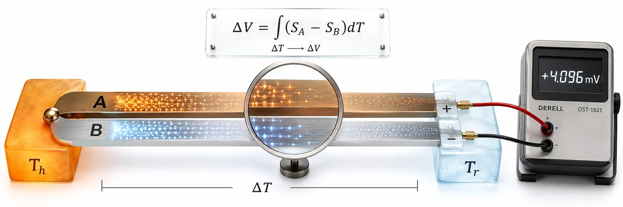
The Seebeck effect is the generation of a thermoelectric voltage in a conductor or semiconductor when a temperature gradient exists along it. In a circuit made from two different materials, the difference between their thermoelectric behaviour produces a measurable EMF. This is the fundamental operating principle behind a thermocouple.
In simple terms: when two different thermoelectric conductors experience a hot region and a colder reference region, the circuit produces a small voltage. A temperature controller, transmitter or PLC measures that millivolt-level signal and converts it into temperature using the correct thermocouple reference function.
One important correction to many simplified explanations is that the thermocouple voltage is not created only at the welded “hot junction.” The total thermoelectric EMF arises from the behaviour of the conductors through the regions where a temperature gradient exists.
How does the Seebeck effect occur?
When different parts of a material are at different temperatures, the energy distribution of its charge carriers is not uniform. This can create a thermoelectric electric field along the material.
The strength and polarity of this response are described by the material's Seebeck coefficient, usually expressed in microvolts per kelvin or microvolts per degree Celsius.
A practical thermocouple uses two materials with different Seebeck coefficients, allowing the difference between them to appear as a measurable EMF.
How can Seebeck voltage be expressed?
For two thermoelectric materials A and B, the thermocouple EMF can be represented conceptually as:
E = ∫(SA − SB) dT
where:
E: thermoelectric EMF
SA and SB: Seebeck coefficients of the two thermoelements
dT: temperature change.
Because Seebeck coefficients themselves change with temperature, real thermocouple output is nonlinear. Accurate conversion therefore relies on standardized temperature–EMF relationships such as those defined in IEC 60584-1.
Why does a thermocouple use two different materials?
A single homogeneous conductor can exhibit thermoelectric behaviour when a temperature gradient exists, but a useful measurement circuit is formed by combining two materials with different Seebeck coefficients.
For example:
Type K uses nickel-chromium / nickel-aluminium based alloys,
Type J uses iron / copper-nickel,
Type E uses nickel-chromium / copper-nickel,
Type N uses the Nicrosil / Nisil alloy system.
Each pair has a different difference in Seebeck coefficient, so each thermocouple type produces a different EMF at the same temperature.
Is thermocouple voltage produced only at the hot junction?
No. This is one of the most common oversimplifications in thermocouple explanations.
The welded measuring junction electrically joins the two thermoelements, but the total thermoelectric EMF is produced by the behaviour of the conductors through the regions where temperature changes along their length.
This is why contamination, alloy-composition changes or thermoelectric inhomogeneity along a thermocouple wire can shift its calibration even when the welded tip itself remains mechanically intact.
Electrical continuity does not prove that a thermocouple is still measuring correctly.
Does a thermocouple measure temperature or temperature difference?
Fundamentally, a thermocouple generates an EMF related to a temperature difference.
If the measuring region is at Thot and the reference connection region is at Tref, the measured EMF can be represented conceptually as:
Emeasured = E(Thot) − E(Tref)
This is why practical thermocouple instruments use cold-junction compensation (CJC).
Without knowing the reference-junction temperature, the measured millivolt value alone is not enough to determine the correct absolute hot-junction temperature.
Does the “cold junction” actually have to be cold?
No. “Cold junction” is a historical term.
The reference connection may physically be at 20 °C, 30 °C or another temperature. What matters is that its temperature is known accurately and included in the thermocouple calculation.
Standard thermocouple reference data are based on a 0 °C reference junction, so a modern instrument first compensates for the real terminal temperature and then applies the appropriate reference table or polynomial.
What is the thermoelectric effect?
Thermoelectric effects describe reversible relationships between temperature, heat flow and electrical transport.
The three classical thermoelectric effects are:
Seebeck effect — a temperature difference produces thermoelectric EMF.
Peltier effect — electrical current causes reversible heat absorption or release at a junction between different materials.
Thomson effect — electrical current flowing through a homogeneous conductor with a temperature gradient produces reversible distributed heating or cooling.
These are different observable effects, but they belong to the same thermoelectric framework.
How does the Seebeck effect generate electrical power?
In a thermoelectric generator, many p-type and n-type semiconductor elements are arranged electrically and thermally to create a useful voltage.
When one side of the module is kept hot and the other side cold, the Seebeck effect creates an electrical potential difference.
When a load is connected, current can flow and part of the available thermal energy can be converted into electrical power.
This principle is used in applications such as waste-heat recovery, specialized remote power systems and radioisotope thermoelectric generators.
What is the difference between the Seebeck and Peltier effects?
The two effects are closely related, but the direction of energy conversion is different.
Seebeck effect:
Temperature difference → electrical voltage.
Peltier effect:
Electrical current → reversible heat absorption at one junction and heat release at another.
A thermocouple temperature sensor therefore relies primarily on the Seebeck effect, while a thermoelectric cooler is designed around the Peltier effect.
What is the Peltier effect?
The Peltier effect is the reversible absorption or release of heat at a junction between different thermoelectric materials when an electric current passes through the circuit.
Depending on current direction, one junction can absorb heat while another releases heat.
Reversing the current can reverse which side heats and which side cools.
The principle is used in:
thermoelectric coolers · compact electronic cooling · precision optical systems · laser-diode temperature stabilization · laboratory instruments.
A practical Peltier cooler is not governed by the Peltier effect alone. Electrical resistance produces Joule heating, and ordinary thermal conduction also transfers heat from the hot side back toward the cold side.
Can a Peltier module be used for temperature control?
Yes. Controlling the current through a Peltier device can move heat in either direction and regulate the temperature of a component or surface.
In a real closed-loop system, temperature may be measured using a Pt100, thermistor or another temperature sensor, while a temperature controller or PLC regulates the Peltier current.
The Peltier element is therefore an actuator, not the temperature sensor itself.
What is the Thomson effect?
The Thomson effect is reversible heating or cooling distributed along a homogeneous conductor when electrical current flows through it while a temperature gradient is present.
Unlike the Peltier effect, it does not require a junction between two different materials.
The magnitude and sign of Thomson heating depend on:
current · temperature gradient · the material's Thomson coefficient.
Whether a particular section absorbs or releases heat depends on the material and the relative directions of current and temperature gradient. It is therefore not correct to use one universal “cold-to-hot always heats, hot-to-cold always cools” rule for every conductor.
Is the Thomson effect the same as Joule heating?
No.
Joule heating is the irreversible electrical heating associated with resistance:
P = I2R
and does not reverse sign when current direction is reversed.
The Thomson effect is reversible and depends on both current direction and temperature gradient.
How are Seebeck, Peltier and Thomson effects related?
The three classical thermoelectric effects are not unrelated coincidences. They are different manifestations of coupled heat and charge transport.
Thermodynamic relations connect the Seebeck, Peltier and Thomson coefficients to one another.
This is why the temperature dependence of a material's Seebeck coefficient is also physically related to its Thomson behaviour and Peltier coefficient.
Which temperature sensors use the Seebeck effect?
The Seebeck effect is the direct basis of thermocouple temperature measurement.
Types K, J, T, E, N, R, S, B, A and C all use different thermoelement combinations and therefore different Seebeck behaviour.
A Pt100 does not work on the Seebeck effect. It measures the temperature-dependent electrical resistance of platinum.
The two technologies are compared in Thermocouple vs Pt100.
Do non-contact temperature sensors use the Seebeck effect?
General industrial non-contact temperature sensors use radiation thermometry rather than a thermocouple measuring circuit.
An IR sensor or pyrometer evaluates thermal radiation arriving from the target, while a thermocouple measures thermoelectric EMF generated by its two conductors under a temperature gradient.
Why is thermocouple output not normally 0–10 V?
The Seebeck voltage generated by a thermocouple is normally only in the microvolt to millivolt range.
For this reason, connecting a thermocouple directly to an ordinary 0–10 V analog input is generally not a correct measurement method.
The instrument needs a suitable low-level differential input, correct thermocouple linearization and cold-junction compensation.
Can thermocouple output be converted to 4–20 mA?
Yes. A suitable temperature transmitter or sensor converter measures the thermocouple's low-level EMF, applies CJC and the correct reference function, and converts the temperature into a standard industrial signal.
For example, a transmitter may be configured as:
4 mA → 0 °C
20 mA → 1000 °C
The temperature can then be transmitted over a long cable as 4–20 mA and read by a PLC.
Why can a thermocouple show the wrong temperature?
The Seebeck effect itself is well defined, but the complete installed system can introduce many errors:
wrong thermocouple type
reversed polarity
incorrect extension or compensating cable
CJC error
thermoelectric inhomogeneity
high-temperature drift
electromagnetic interference
poor mechanical installation
The effect of thermocouple wiring is covered in IEC 60584-3 Thermocouple Extension and Compensating Cables.
Can a thermocouple be extended with ordinary copper cable?
Not at any arbitrary point without considering the measurement architecture.
The point where thermocouple conductors are changed to copper can effectively move the reference-junction region. If the instrument does not know the temperature of that transition, additional thermoelectric error can result.
Correct extension or compensating cable should therefore be used where required.
Can VFDs interfere with a Seebeck signal?
A VFD does not change the Seebeck effect itself, but electromagnetic interference can be coupled into the thermocouple's very small millivolt-level signal.
Thermocouple cable routed beside VFD motor leads, servo cables or high-power switching conductors can produce unstable or noisy temperature readings.
Signal and power wiring should therefore be separated appropriately, shielding and grounding should be designed correctly, and a local transmitter can be useful in electrically noisy environments.
Why is the Seebeck effect important in temperature measurement?
The Seebeck effect makes it possible to build small, rugged and fast temperature sensors that do not require external excitation at the sensing junction itself.
Thermocouples can therefore be used in:
industrial furnaces · motors · plastics machinery · metal processing · power generation · turbines · laboratories · cryogenic systems · specialized measurements above 2000 °C.
The correct sensor should be selected by comparing the properties of the available thermocouple types rather than assuming one type is suitable for every temperature range and atmosphere.
Conclusion
The Seebeck effect is the development of thermoelectric voltage associated with a temperature gradient, with a measurable thermocouple EMF resulting from the difference between the thermoelectric behaviour of two materials.
A thermocouple should not be described merely as “two metals generating voltage at a welded junction.” The actual EMF depends on the integrated thermoelectric behaviour of the conductors through their temperature-gradient regions.
Understanding the Seebeck effect also explains why cold-junction compensation, correct thermocouple wiring, thermoelement homogeneity, standardized reference functions and correct instrument linearization are essential for reliable temperature measurement.
Seebeck, Peltier and Thomson are three related thermoelectric effects: Seebeck links temperature difference to electrical voltage, Peltier links electrical current to reversible junction heat transfer, and Thomson links current plus temperature gradient to reversible distributed heating or cooling within a conductor.
Related thermocouple and temperature measurement topics
+ What Is a Thermocouple? · Types of Thermocouples
+ Type K Thermocouples · Type J Thermocouples · Type N Thermocouple
+ Cold-Junction Compensation · Thermocouple Standards
+ Pt100 Sensors · Thermocouple vs Pt100
+ Non-Contact Temperature Sensors · Temperature Sensor Converters