
What is PTC sensor?
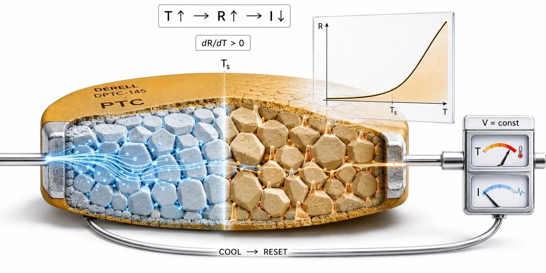
PTC (Positive Temperature Coefficient) describes a temperature-sensitive resistive element whose electrical resistance generally increases as temperature rises. In industrial temperature protection, the term “PTC sensor” often refers to a ceramic PTC thermistor whose resistance rises very sharply when a specified temperature region is reached.
In simple terms: when a PTC sensor gets hotter, its resistance increases. In many motor-protection PTCs the resistance remains relatively low through normal operating temperatures and then rises rapidly around a defined switching or sensing temperature. A relay, electronic circuit or PLC system can detect that change and generate an alarm or protective shutdown.
PTC devices are used in several different ways, including over-temperature protection, motor-winding protection, electronic thermal monitoring, overcurrent limitation and self-regulating heaters. Not every PTC device is designed for the same purpose, and not every PTC should be treated as a precision temperature-measurement sensor.
What does PTC mean?
Positive Temperature Coefficient means that the resistance has a positive temperature coefficient over the relevant operating region.
In simplified form:
Temperature ↑ → Resistance ↑
A NTC thermistor behaves in the opposite direction:
Temperature ↑ → Resistance ↓
The broader product family can be found under PTC / NTC temperature sensors.
How does a ceramic PTC thermistor work?
Many classic switching PTC thermistors used for motor and over-temperature protection are based on semiconducting ceramic materials derived from barium titanate (BaTiO3).
The electrical behaviour of the ceramic changes strongly in a particular temperature region. Below that region, resistance can remain comparatively low. As the sensor approaches its characteristic switching region, resistance can increase by several orders of magnitude over a relatively small temperature interval.
This sharp transition makes a switching PTC especially useful for answering the practical question:
“Has the protected component exceeded its permitted temperature?”
rather than necessarily providing a highly linear continuous temperature value.
Is PTC resistance linear with temperature?
Usually not. This is particularly true for ceramic switching PTC thermistors.
The resistance may change only modestly over one temperature region and then rise extremely rapidly around the sensing or switching temperature.
For this reason, representing a switching PTC as a straight resistance-versus-temperature line can be misleading.
PTC and NTC resistance–temperature behaviour
Schematic PTC vs NTC R/T Curves
The graph illustrates the operating principle only. Actual resistance and temperature values depend on the individual component datasheet.
What is the PTC switching temperature?
A switching PTC is designed so that its resistance rises dramatically around a defined temperature region.
Datasheets may use terms such as switching temperature, sensing temperature, reference temperature or Curie temperature.
These expressions should not automatically be treated as identical without reading the manufacturer's definition. The actual R/T curve and specified sensing point should always be checked.
Is a PTC used for precision temperature measurement?
Some positive-temperature-coefficient sensors can be used for temperature measurement, but classic ceramic switching PTCs are often better suited to threshold detection than to highly accurate continuous thermometry.
In a motor winding, for example, the important information may not be whether the winding is exactly 112.3 °C or 113.1 °C. The key requirement may simply be to detect that a permitted thermal limit has been reached.
Where continuous and more precise temperature measurement is required, a Pt100, Pt1000, NTC or suitable thermocouple may be more appropriate.
Is PTC the same as Pt100?
No. Both may exhibit increasing resistance with temperature, but their construction and measurement behaviour are very different.
A Pt100 is a platinum RTD with a nominal resistance of 100 Ω at 0 °C and a standardized resistance–temperature characteristic intended for quantitative temperature measurement.
A ceramic switching PTC can instead produce a very steep resistance rise around a designed threshold temperature.
Pt100 → quantitative temperature measurement
Switching PTC → strong indication that a temperature limit has been exceeded
is a useful first distinction in many industrial applications.
What is the difference between PTC and NTC?
NTC and PTC thermistors are both temperature-sensitive resistors, but their resistance changes in opposite directions.
PTC: resistance generally increases as temperature rises.
NTC: resistance decreases as temperature rises.
An NTC often provides a continuously varying R/T curve over a broad temperature range and is widely used for electronic temperature sensing and compensation.
A switching PTC can provide a very abrupt resistance increase around a thermal limit, which makes it particularly useful for over-temperature protection.
How is a PTC used for motor protection?
One of the most important industrial applications of PTC thermistors is electric-motor winding protection.
The PTC sensor is embedded in or placed close to the winding where it can follow the temperature of the critical hot spot.
During normal operation the sensor resistance remains comparatively low. When winding temperature approaches the specified PTC switching region, resistance rises sharply.
A PTC protection relay or suitable electronic input can detect this change and:
generate an alarm
stop the motor
open a contactor
command a thermal trip through a VFD
or pass the protection status to a PLC.
The PTC does not physically cool the motor. It detects excessive winding temperature so that the protection system can act.
Why are several PTC sensors used in a three-phase motor?
A single sensing point may not represent the hottest part of every motor winding.
For three-phase motor protection, PTC thermistors can be placed in different phase windings and connected in series.
If any one sensor reaches its switching region, total series resistance increases sharply and the protection relay can issue a trip command.
This approach is widely associated with motor-protection PTC systems and standards such as DIN 44081 / DIN 44082.
How can a PTC be used in refrigeration or cooling control?
An increase in PTC resistance does not directly cool an evaporator, refrigerator or other process.
The resistance change must first be detected by an electronic control circuit. A cooling controller can then operate a compressor, fan, valve or another actuator.
The functional chain is therefore:
PTC sensor → sensing / threshold circuit → controller → actuator
rather than “PTC resistance rises and the machine automatically becomes cooler.”
How does a self-regulating PTC heater work?
Some ceramic PTC elements are intentionally designed not as sensors but as self-regulating heaters.
When the element is cold, resistance is relatively low and more current flows. Electrical power heats the PTC.
As the element approaches its switching region, resistance rises strongly. Current and electrical heating power then decrease.
This natural feedback can limit the operating temperature without requiring the PTC material itself to behave like a conventional thermostat.
PTC heaters are used in applications such as compact air heaters, automotive auxiliary heating and electronic thermal management.
How is PTC used for overcurrent protection?
When excessive current passes through a resistive PTC element, its own I²R heating increases its temperature.
If the element reaches the switching region, resistance rises sharply and the current can be strongly limited.
This behaviour is used in certain current-limiting and protection applications.
A temperature-sensing PTC and a current-limiting PTC should not automatically be treated as the same product. The device must be selected for the application stated in its datasheet.
Is a ceramic PTC the same as a polymer PTC?
No. Both can exhibit positive temperature coefficient behaviour, but their structures and common applications are different.
Ceramic PTC: commonly based on semiconducting barium-titanate ceramics. Used for temperature sensing, motor protection, current limitation and self-regulating heating depending on the component design.
Polymer PTC / PPTC: a conductive-polymer device widely used as a resettable overcurrent protector.
A PPTC is not normally the same thing as a precision process-temperature sensor.
Are PTC thermistors usually made from polymers?
No. That statement is too broad.
Many classic PTC thermistors used for motor protection and switching-temperature detection are ceramic devices.
Polymeric PTC devices form a separate family strongly associated with resettable overcurrent protection.
Is thin-film PTC a separate operating principle?
Terms such as thin film, SMD, disc, probe and leaded often describe construction or packaging rather than a completely separate PTC physical principle.
For example, compact SMD ceramic PTC devices can be designed for over-temperature detection in electronic circuits.
It is therefore more useful to classify a PTC by its material system, R/T characteristic and intended function than to assume that package shape defines its electrical behaviour.
Are metal resistance sensors also PTC devices?
Platinum and many metallic conductors have a positive temperature coefficient of resistance in the physical sense.
However, industrial terminology normally classifies a Pt100 as an RTD, while “PTC thermistor” usually refers to a semiconductor thermistor device.
This distinction matters when selecting the PLC or controller input. A Pt100 RTD input and a motor-protection PTC input are not interchangeable.
Can a PTC be connected directly to a PLC?
It depends on the PLC input.
Connecting a PTC directly to an ordinary 24 V digital input is usually not the correct method. The PLC needs either a dedicated PTC/thermistor input or an external sensing and threshold circuit.
A common motor-protection architecture is:
PTC → PTC protection relay → PLC / contactor / VFD
If a numerical temperature value is required, electronics designed for the actual PTC characteristic or a suitable temperature sensor converter may be required.
Can a PTC be connected to an analog input?
A PTC is a resistance device; it does not generate a standard analog voltage or current output by itself.
To use it with a normal analog input, the resistance must first be converted into a suitable voltage, current or digital signal.
With suitable electronics, the temperature or protection information can be transferred to the control system using 4–20 mA or 0–10 V.
What is PTC self-heating?
When current flows through a resistive element, electrical power is converted into heat:
P = I2R
If a PTC is being used as a temperature sensor, excessive measuring current can warm the element above the real temperature of its surroundings.
This is called self-heating and can create measurement error.
In a PTC heater or overcurrent-protection device, on the other hand, self-heating can be an intentional part of the operating principle.
Can a PTC sensor be checked with a multimeter?
A basic check is possible.
The sensor resistance can be measured at room temperature and compared with the expected datasheet value.
When the sensor is heated in a controlled way toward its switching temperature, a strong resistance increase should be observed for a switching PTC.
However, simply measuring “some resistance” at room temperature does not prove that the sensor trips correctly at the required temperature.
For motor protection, testing the PTC together with its protection relay provides a more meaningful functional check.
What PTC faults can occur?
Common field problems can include:
open-circuit sensor
broken lead wire
short circuit
incorrect PTC switching temperature
poor thermal contact with the protected hot spot
incompatible PTC relay or electronic input
self-heating caused by excessive measuring current
incorrect series or parallel connection
Which standards are used for PTC thermistors?
IEC 60738-1 defines general terminology and test methods for directly heated thermistors with a positive step-function temperature coefficient.
Motor-protection PTC systems are also commonly associated with standards such as DIN 44081 and DIN 44082.
A standard name alone is not enough to select the correct component. Important datasheet parameters include:
sensing / switching temperature
R/T characteristic
nominal resistance
permitted measuring voltage and current
maximum operating temperature
mechanical construction and insulation
compatible relay or electronic input
What should be specified when selecting a PTC sensor?
When choosing a PTC sensor, determine at least:
whether the application is temperature sensing, overcurrent protection or heating
required switching temperature
normal ambient temperature
nominal resistance
R/T curve
measuring current
sensor dimensions
lead and insulation type
compatibility with the PLC, VFD or protection relay
Advantages of PTC thermistors
In the correct application, a PTC can:
provide a very strong indication of a defined over-temperature condition
work with relatively simple protection electronics
be manufactured small enough for embedding in motor windings
allow several sensors to be connected in series for multi-point protection
provide self-regulating heating or resettable protection in specialized PTC designs
Limitations of PTC thermistors
Important limitations include:
many ceramic PTCs have a strongly nonlinear resistance–temperature curve
not every PTC is suitable for precision continuous temperature measurement
switching temperature and R/T characteristics are product-specific
self-heating must be considered
direct connection to a standard PLC analog input is often not possible
Conclusion
A PTC thermistor is a temperature-sensitive resistive device whose resistance increases with temperature, but it should not automatically be treated as a linear temperature sensor.
Many PTCs used for motor and electronics protection are barium-titanate-based ceramic devices whose resistance rises extremely rapidly around a defined switching temperature.
This makes PTC particularly useful for motor-winding over-temperature protection, thermal limit detection, current limitation and self-regulating heater applications.
Where accurate continuous process temperature is required, the actual R/T characteristic of the PTC must be evaluated and alternatives such as Pt100, Pt1000, NTC or thermocouple may be more appropriate among the available temperature sensors.
Related PTC, NTC and temperature measurement topics
+ PTC / NTC Sensors · PTC Sensors · NTC Sensors
+ Pt100 Sensors · What Is Pt1000? · What Is a Thermocouple?
+ All Temperature Sensors · Temperature Sensor Converters
+ Temperature Controllers · Cooling Controllers · PLC Systems