
How can the defrost control mechanism be replaced or repaired?
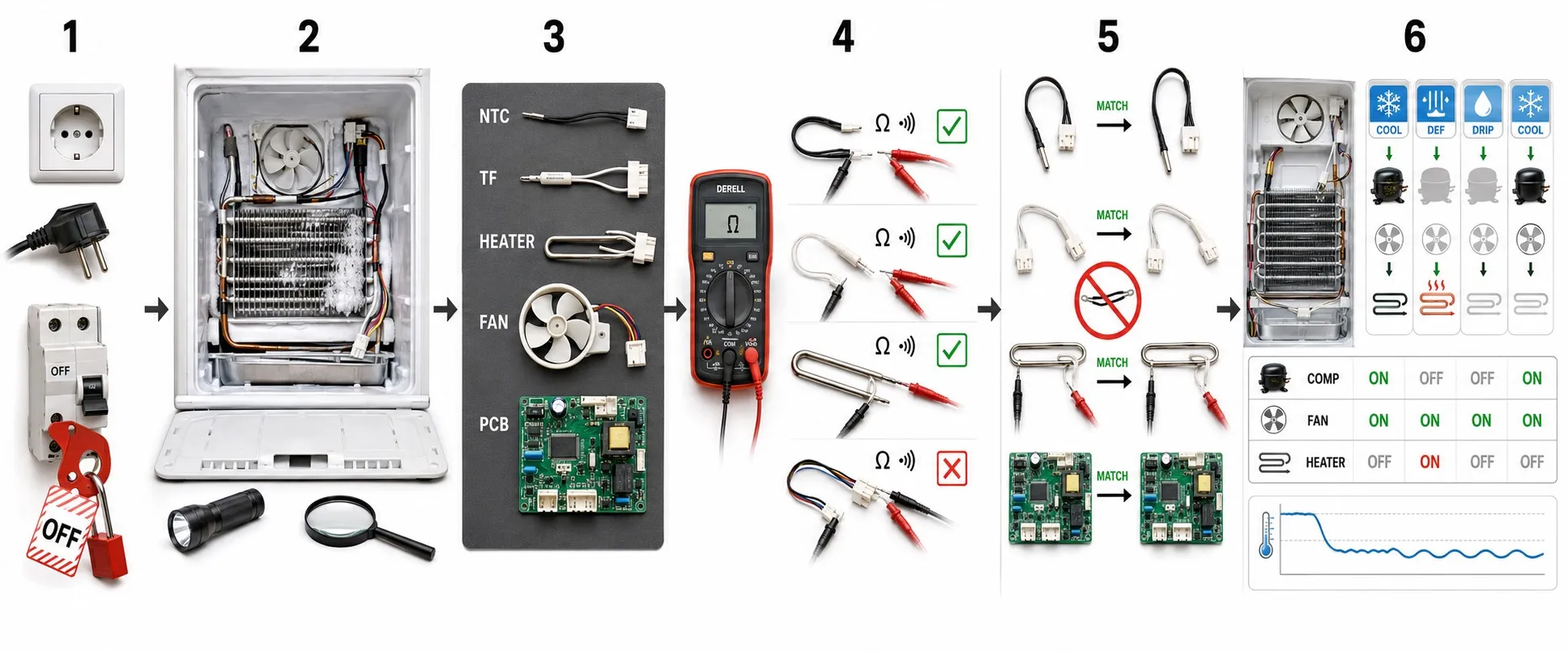
How is a defrost control repaired or replaced?
Repairing a defrost control involves identifying the failed component, selecting a compatible replacement and verifying the complete cycle. Ice buildup in a refrigeration system does not establish that the controller has failed. Electrical disconnection, wiring and measurements should be carried out by personnel competent to work on the equipment.
Establish the cause first: Record fault symptoms and alarm codes, then assess the probe, wiring, defrost heater, fan, drainage and moisture entering through doors. The effects of defrost failure can resemble heater or fan faults. Replacing the controller without understanding the operating cycle may leave the problem unresolved.
Isolate safely before intervention: Isolate all relevant energy sources, prevent reconnection and prove the work point dead using appropriate test equipment. An “OFF” display or a keypad shutdown is not electrical isolation. Controllers and loads may have separate supplies. Address stored energy and other hazards using the manufacturer’s procedure.
Document the existing arrangement: Record the complete device code, wiring diagram, conductor functions and accessible parameters. Photographs help, but wire colour or an old terminal number is insufficient as a wiring reference. Verify supply, inputs and output assignments against the technical specifications.
Distinguish probe faults from controller faults: NTC and PTC probes cannot be interchanged arbitrarily. Reference resistance and the temperature curve must also match. Assess probe compatibility and cable condition using manufacturer data. A large calibration offset is not a suitable way to disguise an incompatible probe.
Match the replacement to every requirement: When selecting a controller, compare supply voltage, AC/DC type, probe inputs, output count and supported defrost method. A similar brand or model name or front panel is insufficient. For an appliance-specific electronic board, use the manufacturer’s approved spare or a verified equivalent.
Check the load circuit as well: A relay output is not selected by its ampere label alone. Assess switching voltage, load type, compressor starting load and NO/NC contact arrangement. Use a suitable contactor where required, taking account of the difference between a relay and a contactor. Installing a new controller without investigating a damaged output can lead to repeat failure.
Install and wire using the new diagram: Check the panel cutout, body depth, terminal arrangement, conductor size and specified tightening torque. Meet gasket and installation requirements to maintain the IP protection rating. Route probe cables separately from supply and load wiring as specified by the manufacturer. Do not automatically transfer old connections to identically numbered terminals on the replacement.
Verify parameters by function: For defrost settings, check the defrost method first, followed by initiation interval, termination temperature, maximum duration, drip time and fan delay. Review compressor delays, probe selection, input assignments and alarm limits too. Factory defaults are not a commissioned setup; do not copy settings between models merely because parameter codes look similar.
Observe the complete cycle after replacement: Once protective covers and connection checks are complete, commission the system using the manufacturer’s procedure. A supported manual defrost command can be used to test the cycle. Observe initiation, correct output operation, termination, drainage, fan restart and cooling recovery. The importance of defrost control lies in this complete sequence; an illuminated display alone does not establish a successful repair.
Repair or replacement? The decision depends on the fault, manufacturer service policy, parts availability and the ability to validate the repair. Controllers that the manufacturer specifies must not be opened should be referred to the manufacturer or authorised service. Bypassing a thermal limiter, protective device or output is not a repair.
Hand over a documented result: Record the fitted part code, final settings, resolved cause and cycle test result. In applications requiring food safety management, maintain appropriate product storage conditions during service. Monitor energy consumption and temperature recovery during normal operation. Send the removed electronics through an appropriate waste route, taking their environmental impact into account.