
What are the technical specifications of the defrost control mechanism?
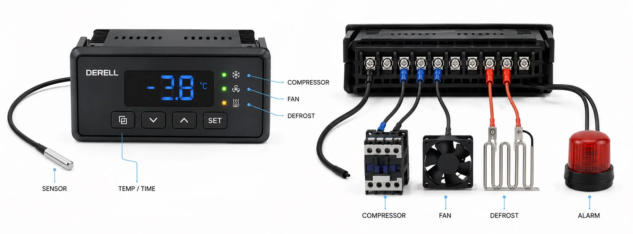
What are the technical specifications of a defrost controller?
A defrost controller’s specifications define the temperatures it can measure, the outputs it can manage and the conditions governing its operation. In a refrigeration control system, a statement such as “supports defrost” is insufficient. Assess probe inputs, load ratings, timing functions and mechanical installation together. Obtain exact values from the data sheet for the complete ordering code.
Defrost method and initiation: Establish which defrost methods are supported: off-cycle, electric or hot gas. Automatic and manual initiation can involve intervals, schedules, accumulated operating time or external commands. A demand algorithm does not necessarily measure ice thickness directly.
Supply voltage and controller consumption: Supply specifications include voltage, AC/DC type, frequency and permitted tolerance. The controller’s own consumption may be stated separately in W or VA. Supply voltage, controller consumption and relay load current are different quantities. A relay’s ability to switch a 16 A load does not mean that the controller itself consumes 16 A.
Output count and load ratings: Independently managing the compressor, defrost and fan requires a suitable number of relay outputs. Check each output’s ampere rating, switching voltage, load type and NO/NC contact arrangement. Compressor starting load matters alongside running current. Use a suitable contactor where the load exceeds the output rating; account for the difference between a relay and a contactor when selecting the switching arrangement.
Probe inputs and compatibility: NTC or PTC alone does not fully specify a probe: reference resistance and the temperature curve must also match. Some models support other inputs, such as PT1000. Check probe compatibility, input count and cabinet/evaporator assignments together. The difference between a sensor and a thermostat helps distinguish the measuring element from the controller making operating decisions.
Measuring range, resolution and accuracy: Range defines the readable temperature limits, resolution defines the display increment, and accuracy defines the error limit under stated conditions. 0.1 °C resolution does not mean ±0.1 °C accuracy. In a specification such as “±0.7 °C ±1 digit”, the digit refers to the least significant displayed step. Check whether the stated accuracy includes probe tolerance.
Termination conditions and maximum duration: Defrost can finish by time or when the evaporator probe reaches the defrost termination temperature. A maximum duration also limits a temperature-terminated cycle. Defrost interval and defrost duration are different parameters; consult the manual to establish whether the interval is measured between cycle starts or uses another time basis. Understand this logic before changing defrost settings.
Drip time and fan management: A pause after the heater switches off may be needed for drainage. Fan restart can depend on time, evaporator temperature or combined conditions defined by the model. Assess compressor minimum-off time and restart delays separately. Identical time values do not necessarily produce identical sequences on different controllers.
Digital inputs: Inputs may support a door switch, external alarm, defrost command or standby function. A volt-free contact input is different from an input designed to receive an applied voltage. Confirm electrical input type, contact polarity and assignable functions. On some controllers, a terminal can serve as either a probe input or a digital input, limiting simultaneous use.
Alarms and probe-failure behaviour: High/low temperature, probe-failure and external-alarm functions vary by model. When assessing fault symptoms, check what the outputs do during the alarm as well as the alarm code. Following a probe failure, different controllers may stop the compressor or run it on timed cycles. Check compatibility of these behaviours when replacing a controller.
Operating protection and independent safety: Maximum defrost duration and compressor delays are useful operating functions. However, a standard operating controller is not automatically equivalent to an independent safety device. Any separate heater temperature limiters and protective arrangements must follow the equipment design and applicable requirements.
Operation after a power interruption: Retaining parameters in memory and resuming an interrupted cycle are different capabilities. Check startup delay, the timing of the first defrost and compressor restart conditions separately. Memory retention does not guarantee that every controller resumes the previous cycle at the point where power was lost.
Installation and environmental conditions: Read front dimensions, panel cutout, body depth, terminal type and conductor size as separate specifications. The IP protection rating may differ between the front and rear; an IP65 front does not make the entire controller IP65. Check ambient temperature, humidity and condensation limits. A wide probe measuring range does not establish the same ambient operating range for the electronics.
Communications and parameter transfer: Where Modbus/RS485 communication is offered, determine whether it is built in or requires an additional interface. Assess Modbus RTU support using the protocol, address, baud rate and register map together. A programming key or TTL connection should not be treated as a direct RS485 port. Confirm supported accessories and simultaneous-use conditions in the manual.
Efficiency functions: Some models offer defrost on demand, fan cycling or night mode. Their effect on energy consumption depends on the application and settings. Availability of a feature does not establish identical savings in every system. Include the probes and inputs needed to use the function in your assessment.
How should the final choice be made? When selecting a control method, document the existing supply, probe arrangement, loads and operating sequence. Then compare brands and models against the same requirements. A matching front panel or similar model name does not establish identical supply, wiring or load capacity.