
What is a countdown time relay?
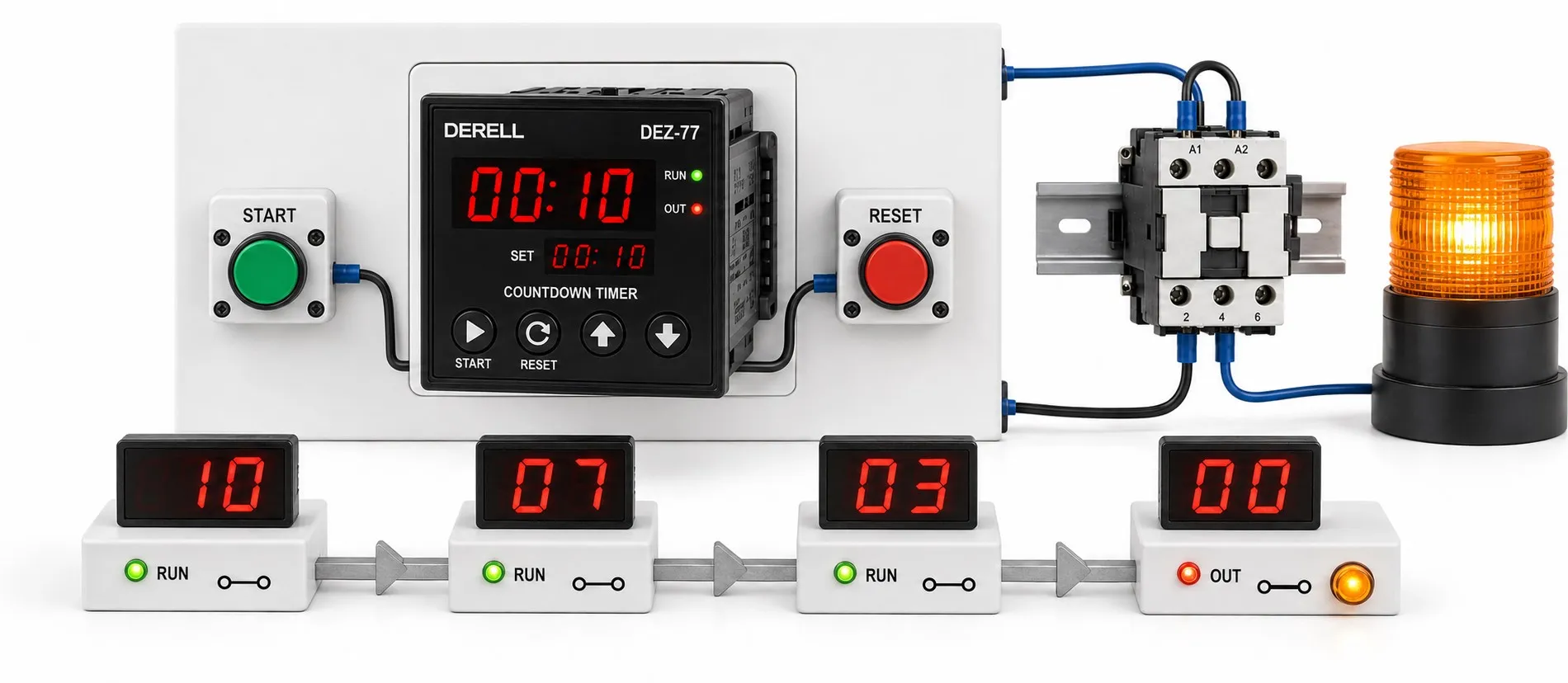
Distinguishing elapsed time from counted input events
A counter/timer relay and a countdown time relay perform different functions, even though their names are sometimes confused. A timer evaluates time, while a counter counts valid input pulses. A countdown timer progresses from a preset duration towards zero; decreasing numbers on its display do not establish that it can count products.
Multifunction counter/timers may provide timer, counter or combined operating modes. These capabilities depend on the specific model. Having both functions in one device does not mean they always operate simultaneously and independently.
Waiting 30 seconds is different from counting 30 products
Timing example: After a process starts, the display may count down from 30 seconds. Depending on the selected operating mode, an output may energise when the time expires, or an output energised at the start may switch off. The countdown display direction does not, by itself, determine the output switching sequence.
Counting example: If a sensor produces one valid pulse per product, a counter reaches its target after 30 pulses. A slower conveyor takes longer to reach that target; a faster conveyor takes less time. There is no fixed relationship between 30 products passing and 30 seconds elapsing.
A sequence such as “count 30 products, wait 5 seconds, then activate an output” requires counting and timing logic. Use a device explicitly supporting that sequence or a suitable PLC program. An ordinary countdown timer should not be assumed to provide it.
Editor’s note: A countdown timer, pulse counter and operating-hours meter serve different purposes. An operating-hours meter may display accumulated running time without providing a preset timed output. Before selecting equipment, establish whether you need to measure a duration, count events or monitor accumulated operating time.
Start, reset and pause inputs
A start input initiates the timing cycle according to the selected mode. Reset returns the current timing or counting value to its defined starting condition. Inputs called gate, inhibit or hold may pause timing or prevent counting, depending on the model. Do not assume these labels imply identical behaviour: check input priorities and required signal durations in the manual.
Counters may offer up counting, down counting or bidirectional counting. Whether the output remains latched, produces a timed pulse or automatically resets the cycle depends on the output operating mode. Entering a target number alone does not define all these behaviours.
Why sensor compatibility and counting speed matter
Inputs may accept dry contacts, NPN or PNP signals; the required setting and wiring must be verified. The NPN–PNP distinction describes the electrical interface. NO–NC describes output logic relative to the sensor’s detection state; these are separate characteristics. Device supply voltage and the permissible counting-input signal level are also different specifications.
A signal from an inductive sensor or mechanical switch may be interpreted as several pulses because of contact bounce or electrical noise. For excessive counts, investigate filtering and signal quality; for missed counts, check minimum pulse width and maximum input frequency. Stronger filtering may also reject short valid pulses, so it is not automatically the best setting.
For example, an encoder producing 100 pulses per revolution at 600 rpm generates 1,000 pulses per second on one channel. An input configured for only 30 pulses per second cannot count that signal correctly. Assess the need for a high-speed counter across the complete signal chain. The method used to evaluate A/B channels can also affect the resulting count.
What is retained after a power interruption?
Retaining the setpoint, retaining the current count or remaining time and restoring the output state after power returns are separate capabilities. One device may remember the target duration but reset the active cycle; another may resume from a retained timing value. The word “memory” does not establish that every operating state is preserved.
During commissioning, verify start, pause, reset and power-restoration behaviour. Display resolution should also be distinguished from timing accuracy: showing small time increments does not mean the total timing error is limited to that increment.
Select the output for the actual load and application
Relay contacts and transistor outputs require different interfaces. Consider output type, load voltage, starting current and switching frequency together. Motors, heaters or larger valves may require a suitable contactor, interposing relay or power switching device; a single current rating printed on the device should not be applied indiscriminately to every load type.
Typical applications include packaging, part counting, dosing cycles, drying periods and maintenance-time monitoring. However, ordinary process counters and timers do not provide the same functional assurance as safety-related timing relays. An emergency-stop or protective-gate safety function should not depend solely on an ordinary timer.
Related topics: from timing to counting applications
Basic operating principles: How a time relay works, simple time relays and analog time relays help compare adjustment methods and output behaviour.
When the output changes state: On-delay timers, off-delay timers and flasher time relays distinguish delayed operation, delayed release and repeating cycles.
More advanced sequences: Multifunction time relays, programmable time relays and real-time clock relays address different needs; operating for a duration differs from operating at a particular time of day.
Selecting the quantity to measure: A stopwatch concerns elapsed time, while counters and tachometers help distinguish pulse totals from speed measurement.
Installation and troubleshooting: Time relay selection and installation, parameter settings and fault finding support checks of operating modes and input conditions.
Comparing products: When reviewing counter and tachometer prices and timer prices, compare input types, counting speed, retention behaviour and output configuration alongside cost.