
What is an Off Delay Timer?
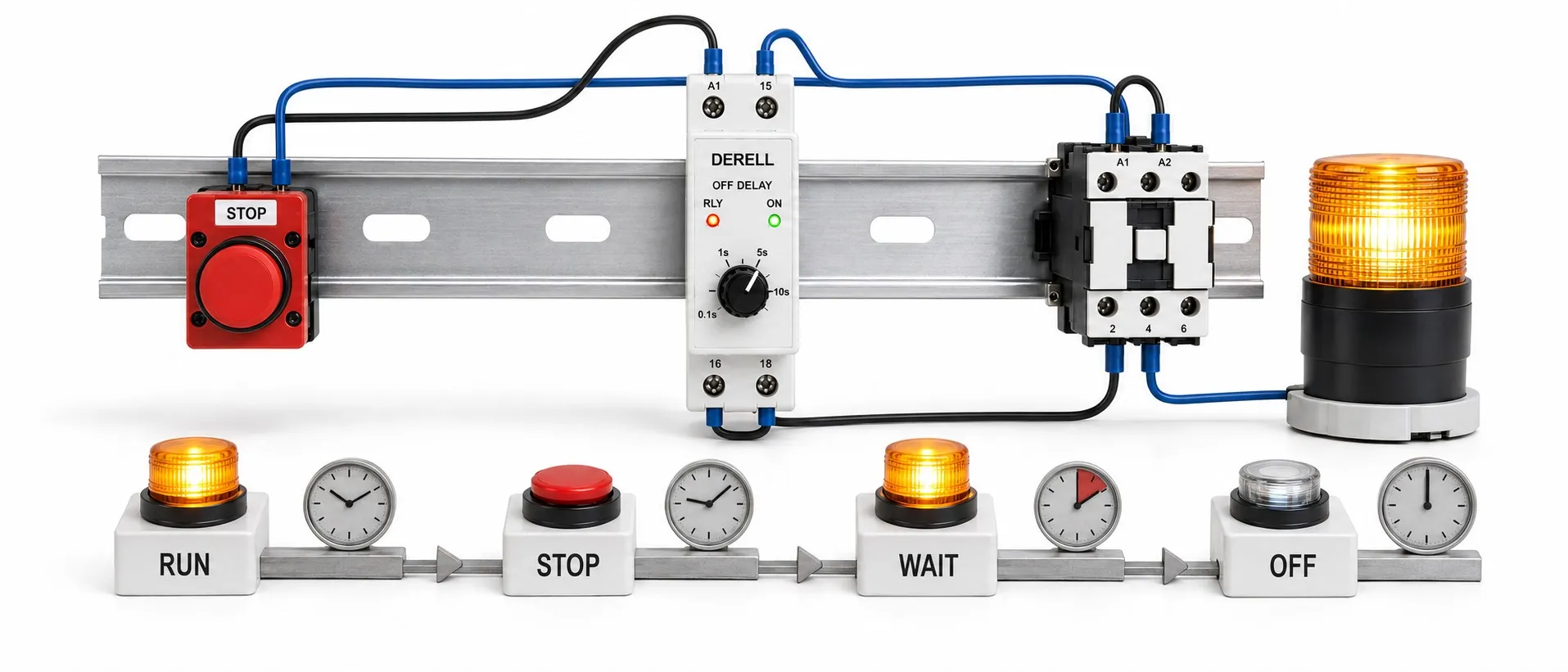
Continued operation after the command ends
OFF-delay is a timing function that keeps an output active for a selected period after its control condition disappears. A fan, for example, can continue running for 30 seconds after its run command is removed. The timer relay releases its output when that period ends. The delay follows command removal rather than command application.
Editor's note: Removing the control signal and removing the timer's supply are different events. Many OFF-delay relays with a separate control input need a continuous supply to complete their delay. If timing must follow supply removal, choose a model explicitly designed for that function. Cutting power to an ordinary timer and expecting it to hold its output is a common wiring mistake.
What is the standard operating sequence?
In basic signal-controlled operation, the device is already powered. Applying the command activates its output without an additional ON-delay setting. Removing the command starts timing while the output stays active. The output releases at timeout. The manufacturer's specified input detection and relay response times are separate from the selected OFF-delay.
Delayed release does not mean every contact closes at timeout. When the output relay releases, its timed NO contact opens and its NC contact closes. Which contact supplies the load determines the behaviour seen in the circuit.
Two different supply and starting arrangements
OFF-delay with a separate control input: Removing the input starts timing while the supply remains present. Follow the supply and control input separately in the wiring diagram. Cutting the entire device supply instead of its command may prevent the expected delay and release the output immediately.
Power OFF-delay: A purpose-built power OFF-delay timer starts its delay when its own supply is removed. Such devices may specify a minimum powered period and conditions for repeated operation. Depending on the device design, a separate reset input may or may not be provided; do not assume that every model has one.
Maintaining a contact position does not provide energy to the load. If the fan's or lamp's own power source is also disconnected, holding a contact cannot keep it operating. Continued operation during a power failure must be considered together with the load supply and any suitable backup energy arrangement.
Reading a three-second OFF-delay
The static diagram below shows a model with a continuous supply and separate control input. The command arrives at zero seconds and activates the output. It disappears at two seconds; the output remains active for another three seconds and releases at five seconds. This is an operating example, not a terminal wiring diagram.
What if the command returns during the delay?
With a retriggerable OFF-delay function, the returning command cancels the release countdown and keeps the output active. Removing the command again starts the full delay. For a 30-second setting, if the command returns ten seconds into the waiting period, the next command removal starts a fresh 30-second delay. Verify this behaviour in the selected model's timing diagram.
During adjustment, read the time unit, range and value together. If a separate reset input is provided, check the manual to establish whether it stops timing, releases the output or has another defined effect. Do not generalise one product's retriggering and reset behaviour to every OFF-delay relay.
Selecting the model and output
During selection, establish the triggering event first: removal of the control input or removal of the device supply? Then consider supply voltage, voltage-input or volt-free-contact operation, timing range, load type and mounting method. Do not apply an external voltage to a contact input unless the diagram specifies it.
Analog-adjusted models use dials and selectors; digital models allow numerical settings. Setting resolution, setting error and repeatability are different properties. With multifunction devices, selecting the correct mode matters as much as selecting the correct time; mode letters do not have universal meanings across manufacturers.
Volt-free contacts are switches, not power sources. Assess contact capacity against load inrush current, inductive characteristics and switching frequency. Use a suitable contactor or interposing relay where required. For semiconductor-output models, check AC/DC compatibility, leakage current and thermal conditions separately.
Applications and practical limits
In industrial control circuits, OFF-delay can keep a cooling fan running after a heater's normal shutdown or allow a conveyor to clear after material feeding stops. Such sequential shutdown periods must reflect the process requirements; elapsed time alone does not prove that the conveyor is empty or sufficient cooling has occurred.
Keeping a pump running after a level signal changes is not suitable for every process. Overflow, dry-running or another stopping condition requires more than reliance on a timer. Continued motor operation is also not soft stopping: an OFF-delay relay does not ramp motor speed, current or pressure.
A general-purpose OFF-delay relay must not delay an emergency stop or replace a safety relay. Safety-related delays require suitable safety equipment and a validated design. Several conditions and steps may call for a programmable timer relay or suitable controller, while a simple timer relay may suit one release delay.
How does it differ from other timing functions?
ON-delay delays initial output activation; OFF-delay delays the release of an active output. A flasher repeats on and off periods. Daily clock-based operation calls for a real-time-clock timer, while lighting that follows sunrise and sunset calls for an astronomical time switch. These functions address different requirements.
If the output releases early or never releases
During fault diagnosis, observe three separate conditions: the timer supply, the actual control-input state and the load supply. Immediate release may mean that the supply is being cut instead of the command. Failure to release may indicate a maintained input, retriggering or an incorrect mode. Check the NO/NC wiring and actual contact behaviour as well.
For power OFF-delay models, pay particular attention to minimum powered periods and repeated-operation requirements. An output LED does not prove that the connected load is operating. During commissioning, test command removal, command return before timeout and supply loss separately.
Related products and topics
Timer relays, analog timer relays, timer relay prices and timer relay types.