
What is an On Delay Timer?
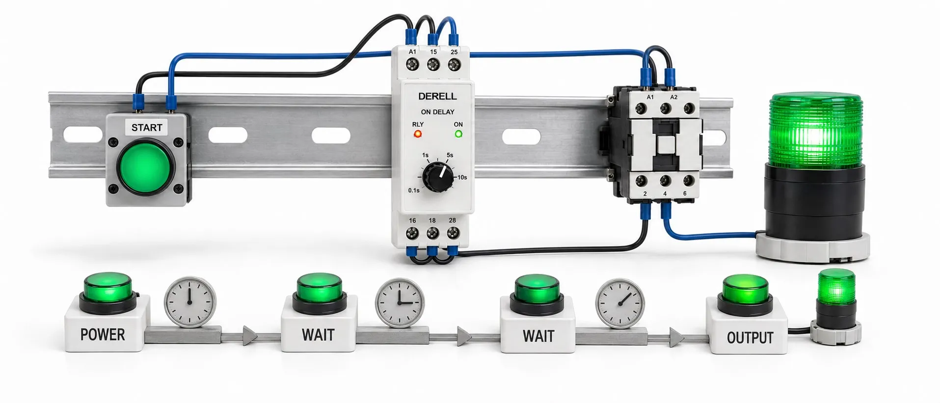
A controlled wait after the command arrives
ON-delay is a timing function that waits for a selected period after its starting condition occurs. The output activates when that period ends. For example, a timer relay set to three seconds activates its output at the end of the third second, provided the required starting condition remains present. The delay and the load's operating time are separate quantities.
Editor's note: ON-delay describes delayed output activation, not a delayed opening of the NO contact. When the timed relay operates, its NO contact closes and its NC contact opens. Always read the contact's normal state and the timing diagram together rather than relying on the function name alone.
How does a standard non-retentive ON-delay behave?
The operating sequence is straightforward: the starting condition occurs, timing begins and the output activates after the selected delay. It remains active while the condition continues. Removing the condition releases the output and resets timing. If the condition disappears before timeout, the output never activates. This describes standard non-retentive operation; verify the specific input and reset behaviour in the product documentation.
With a three-second setting, an input lasting only two seconds does not complete the delay. When the input returns, the full three seconds starts again; the earlier two seconds is not automatically added. Models that accumulate time or retain it after power loss provide different capabilities.
Try a three-second delay
Start holds the example's input active for six seconds. The output stays off for the first three seconds, then activates. At six seconds the input is removed and the output resets. Reset ends the demonstration at any time; resetting within the first three seconds prevents output activation. This is a timing demonstration rather than an electrical wiring diagram.
Your reduced-motion preference is active, so a static timing diagram is shown instead of animation.
Distinguishing supply from the starting signal
The main sections include the supply, timing circuit, any control inputs and the output. In a power-start model, applying the supply starts the delay. A signal-start model can remain powered while waiting for a separate command. The effect of removing that input depends on the selected function.
When wiring the circuit, establish whether the control input accepts a voltage or a volt-free contact. Do not apply an external voltage to a contact input unless the diagram specifies it. For a PLC command, check whether the PLC output uses contacts or a transistor and whether it is electrically compatible with the timer input. Matching pin counts do not guarantee matching connections.
Selecting time and accuracy
During adjustment, select the function, time unit and range before setting the value. A dial position marked “3” could represent seconds or minutes depending on the scale. The available setting range does not establish timing accuracy; compare the application's permitted error with the specifications.
Analog-adjusted models offer convenient dial setting. Digital models provide numerical adjustment and, on suitable products, remaining-time indication. Assess setting resolution, setting error and repeatability separately. With a multifunction device, selecting the wrong mode produces a different result even if the time value is correct.
How does the output control the load?
Volt-free contacts do not generate a voltage; they open or close a path in an external circuit. An NO contact closes when the output activates, while an NC contact opens. Some products provide instantaneous contacts alongside timed contacts. Identify each terminal's function from the product diagram.
During model selection, consider more than the headline contact current rating. Load type, inrush current, switching frequency and electrical life all matter. Use a suitable contactor for a motor or high-power load where required. With semiconductor-output timers, check AC/DC compatibility, leakage current and load wiring separately.
Applications and practical limits
In control circuits, ON-delay can postpone a second machine's command, introduce a short wait after power-up or require a signal to remain present for a defined period. Sequential starting can reduce simultaneous load starts, but the correct process sequence must be established for the application.
Delaying a motor start does not provide soft starting. A timer relay does not ramp motor current, speed or pump pressure. It also does not establish whether a conveyor is actually running or a fan is delivering sufficient airflow. Use suitable feedback where the process depends on those conditions.
Several conditions and steps may call for a programmable timer relay or suitable controller; a simple timer relay may suit a single delay. A general-purpose ON-delay relay must not delay an emergency stop or replace a safety relay. A safety-related delay needs equipment suitable for that function and a validated design.
How does it differ from other timing functions?
OFF-delay delays release after a signal disappears. A flasher repeats on and off periods. ON-delay inserts a wait between the starting condition and output activation. The output is not normally expected to produce a brief pulse and switch off automatically when the delay ends.
Daily operation at 08:00 calls for a real-time-clock timer; lighting that follows sunrise and sunset calls for an astronomical time switch. Measuring elapsed time and following a calendar are different tasks.
If the expected delay does not occur
During fault diagnosis, check the supply, selected mode, time unit, starting signal and contact connections. Insufficient reset time may disrupt the next attempt. If the output LED is on but the load does not operate, inspect the contacts, socket and load circuit separately. Check the manual to establish when setting changes take effect.
Related products and topics
Timer relays, analog timer relays, timer relay prices and timer relay types.