
What is a programmable time relay?
Matching timing and operating sequences to the application
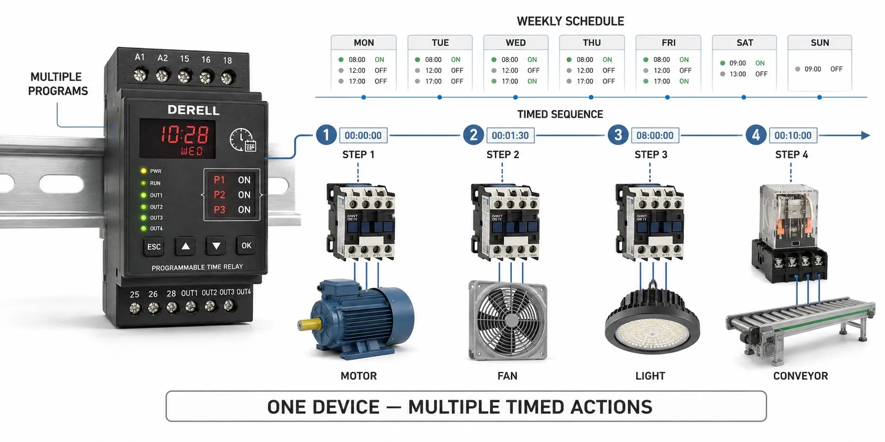
A programmable time relay controls its output according to a selected operating function, preset times and input signals. It performs the basic job of a time relay with more flexible settings: delaying a fan start, operating a valve for a defined period or repeating working and waiting intervals. However, programmable does not mean that every model allows the user to write an unrestricted sequence.
Digital displays, multiple functions and editable logic
Digital generally describes numerical time setting and indication. With a multifunction timer, the user selects from predefined timing modes. More advanced devices may provide independent channels or functions that can be combined. The number of outputs, the number of independent timers and the ability to edit sequence steps are separate capabilities; check the product's timing diagrams.
For example, the Finder 84.02 SMARTimer offers two independently programmable channels and product specific ways of combining functions, with configuration by joystick or NFC. This illustrates how capabilities vary between products. A touchscreen, computer connection, communications protocol or multiple stored recipes should never be assumed to be standard features of all programmable timers.
When does the output actually switch?
With an on-delay function, the output operates after the starting condition and the preset delay. With an off-delay function, it remains active for a period after the appropriate control signal is removed. A function requiring a continuous supply must be distinguished from one triggered by removing the supply. The output does not only change when an entire program finishes: it may switch at the beginning, at the end or repeatedly during timing.
Consider a repeating timing cycle with t1 = 8 seconds on and t2 = 22 seconds off. In a suitable mode that starts with the on interval, the output is active for the first 8 seconds and inactive for the next 22, producing a 30-second cycle. Selecting an off-first mode changes the initial behavior. This could be used for intermittent lubrication or air blowing. Stopping after a specified number of cycles requires a device that explicitly supports cycle counting.
A sequence with several steps is a different requirement. “Wait 3 seconds after detecting a part, open a valve for 5 seconds, then allow 2 seconds to settle” is an illustrative application. A single device can perform it only if its step and output structure supports the sequence. If the next step must also wait for confirmation from a sensor, simply chaining delays is insufficient: conditional control logic is needed.
Start, pause and reset perform different jobs
Start initiates timing; some modes respond to a signal edge, while others depend on a maintained level. Reset clears the timing value and the associated operating state. Pause or Gate may suspend timing while retaining elapsed time in a supported mode. Retriggering may restart or extend the delay when another signal arrives. Whether the output remains active during a pause also depends on the model and function. When configuring timer settings, check the effect of each input as well as the preset time.
Elapsed time and calendar schedules are different
“Operate 15 seconds after a button is pressed” and “operate at 08:00 every weekday” require different capabilities. The second calls for a real-time clock timer or an appropriate calendar function. A weekly time switch such as the Theben TR 610 top3 is an example of that class. For several sensors, interlocks, counters and conditional steps, a programmable control relay may be suitable. More extensive logic and data processing can be handled through PLC programming. Choose according to the complexity of the task.
Resolution, accuracy and power interruptions
A 0.1-second setting increment does not automatically mean an accuracy of ±0.1 seconds. Setting resolution, timing error and repeatability describe different properties. Input detection, output relay operation and the timing base can also affect the actual switching instant. These differences may matter for a short valve pulse, while a ventilation delay lasting several minutes may tolerate a wider variation. Check whether a specified error applies to the set value or to the full timing range.
Editor's note: Retaining settings, retaining elapsed time and reactivating an output when power returns are three separate capabilities. A timer may remember its 60-second preset but discard the 25 seconds that elapsed before an interruption. Another supported mode may resume from the retained value. Do not infer restart behavior from the word “memory”; check the selected mode and its restart conditions.
Define the application before selecting and commissioning
Before selecting and installing a timer, establish the supply voltage, timing range, input type and output arrangement. Do not assume dry contact, PNP and NPN inputs are interchangeable. Two changeover contacts do not necessarily mean two independently controlled channels. A resistive load current rating alone does not establish suitability for switching a motor or coil drawing the same current. Consider an appropriately rated contactor, interposing relay or solid-state driver for the load.
When commissioning a timing circuit, test initial power-up, a short start pulse, a maintained start signal, reset during a cycle and restoration of power. Record whether setting changes take effect immediately or on the next cycle. For unexpected timer behavior, first compare the time unit, mode code, input indication and actual output state. Safety functions such as emergency stopping or guard monitoring require suitable safety equipment; setting a delay on an ordinary timer does not qualify it for those duties.
Related topics
Choosing the device class: A simple time relay may be sufficient for a single delay. When comparing an analog timer with a digitally configured model, consider both adjustment and tolerances. The guide to time relay types helps compare their different operating purposes.
Time or event count? The article on counter and timer functions helps distinguish counting pulses from measuring duration. The difference between a time relay and a timer also explains why a product name alone does not establish its operating behavior.
Special functions and output selection: A star-delta timer requires attention to the transition interval and contactor interlocking. When comparing PWM and pulse generation with slower on/off cycles, consider the required switching rate. A solid-state timer also illustrates the distinction between output technology and timing function.
Expanding the control task: If sensor conditions and process steps need to be added, how a PLC works is a useful starting point. Using timers to improve automation efficiency provides context for reducing unnecessary waits and running auxiliary equipment only when needed.
From fundamentals to product comparison: Review how a time relay operates, then compare timer models against the supply, input, function and output requirements of the application.
Sources
Finder 84 SMARTimer: channels, programming and functions
AutomationDirect CTT: timing charts and power interruption behavior
Eaton easyE4: timer function block and retained values
Theben TR 610 top3: weekly time scheduling
Omron: timing accuracy and technical terminology