
What is an analog time relay?
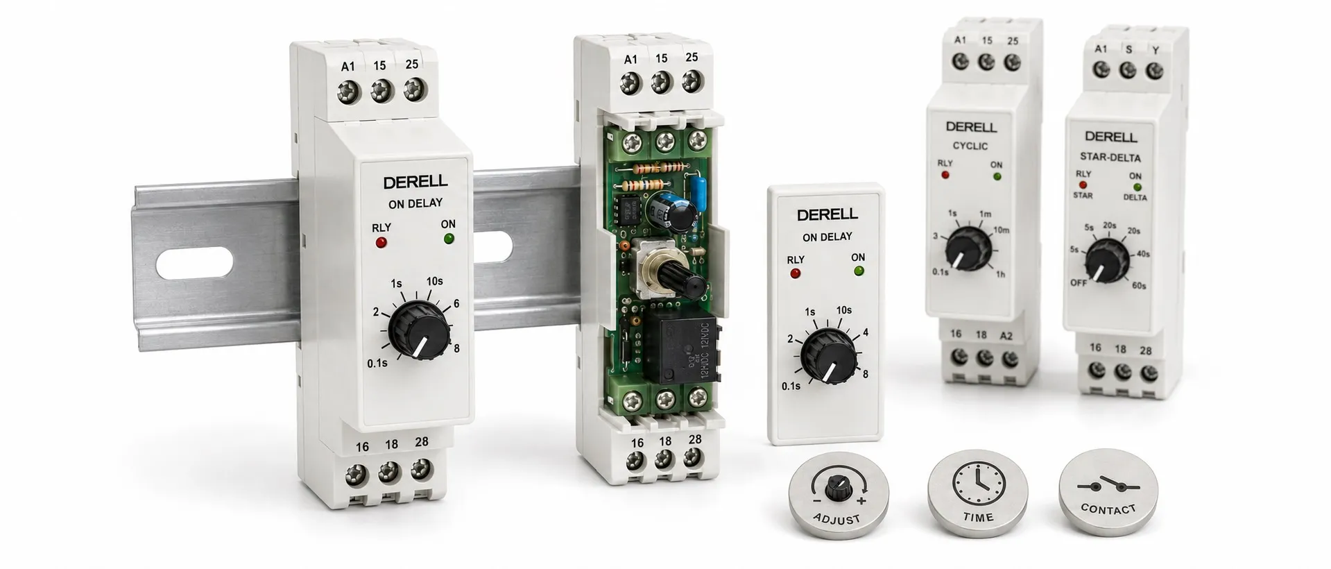
Dial adjustment with electronic timing
Hello. In industrial use, an analog timer relay generally means a timing device whose setting is adjusted using a knob, dial or potentiometer. Once its starting condition is met, it measures time and changes its output according to the selected function. Calling a timer relay “analog” does not mean it must contain gears, springs or a synchronous motor. Many current products in this category use electronic timing circuitry.
Editor's note: The setting method, timing circuit and output technology are separate characteristics. A dial-adjusted device can measure time electronically and then operate mechanical relay contacts. Transistor-output versions may also exist within the same family. Analog adjustment, mechanical timing and contact output are therefore not interchangeable descriptions.
What happens inside the device?
A typical electronic design contains a power supply section, input section, timing section and output stage. These components work together to produce the selected delay. Some designs use an oscillator and counting circuit; a knob on the front does not establish that the internal circuitry is entirely analog. When the timing condition is met, the control circuit commands the relay or semiconductor output.
A mechanical or motor-driven timer can instead measure time using clockwork, a motor or a similar moving mechanism. The behaviour of a spring-wound mechanical device should not be applied to an electronic timer. Electronic models require their specified electrical supply. Turning the setting knob does not provide operating energy.
The expression solid-state timer in a manufacturer's documentation does not always mean the load output is an SSR; it may describe the electronic timing mechanism. To select an actual solid-state-output timer, check whether the output uses relay contacts, a transistor or another semiconductor device.
Which timing functions can it provide?
Delayed energization: In on-delay operation, the starting condition occurs, the set time elapses and the output becomes active. For example, in a suitable circuit, an NO output contact may close approximately five seconds after a control signal becomes active and remains present. What happens if the signal disappears earlier depends on the device's timing diagram.
Delayed de-energization: In off-delay operation, the output can remain active for a period after the control signal is removed. A fan might continue running for 30 seconds after a machine stops. Many signal-triggered models require their supply to remain connected throughout this interval; removing the control signal and removing all power are different actions.
Repeated cycling: A flasher timer relay repeats on and off periods. A requirement for 10 seconds on and 20 seconds off calls for a model allowing independent adjustment of those periods. Not every cyclic timer offers the same setting flexibility.
Star-delta changeover: A star-delta timer must provide the appropriate transition interval as well as the star operating period. An ordinary delay relay lacking the necessary function and output arrangement is not a direct substitute.
How should the time setting be read?
Check the operating function first, followed by the time unit and range, and then the knob position. For example, a device with a 0–10 scale might interpret position “6” as approximately six seconds on its 10-second range, or approximately six minutes on its 10-minute range. This illustrates the principle; actual scales and multipliers depend on the manufacturer. Correct timer adjustment requires more than looking at the main knob.
The setting knob on an electronic analog timer generally does not move like a clock hand to show remaining time. The knob selects the setpoint; any LEDs indicate supply, timing or output status. Check the manual for the meaning of their colours and flashing patterns. Whether a setting change affects the current cycle or the next cycle is also model-dependent.
Accuracy, setting error and repeatability
Setting error is the difference between the selected dial time and the actual operating time. Repeatability describes how closely repeated cycles agree under the same conditions. A device set to 10 seconds might consistently operate at approximately 9.7 seconds. Those results may be repeatable, but the setting error is not zero.
Where a specification uses %FS, calculate the percentage from the stated full-scale value. For a hypothetical 0–10-second scale, ±1% FS means ±0.1 seconds; it is not the same as one percent of a one-second setting. Include any additional millisecond terms and specified supply or temperature effects. Selecting a range appropriate to the required delay makes adjustment easier than working at the very bottom of an unnecessarily wide range.
Supply, triggering and contact wiring
When building a timing circuit, identify the supply connections, any start/reset inputs and the load output separately. 24 V DC and 230 V AC versions are not interchangeable. Some devices start timing when powered; others require a separate starting signal while continuously supplied. Terminal numbering and socket arrangements depend on the model.
If the device has volt-free contacts, those contacts do not generate an output voltage; they open or close an external circuit. A contact's current rating does not give the same switching capability for every motor or coil. Assess load type, inrush current, AC/DC voltage and switching frequency, using a suitable interposing relay or contactor where necessary. Correct selection and installation requires more than matching the number of pins.
Where is it useful, and when is another device needed?
Dial-adjusted timer relays can provide sequential starting, short delays, fan run-on, lubrication cycles and similar electrical control functions. Suitability depends on the required operation and load conditions. A timer can, for example, run a pump for a set period, but elapsed time alone does not measure tank level or detect dry running. Those conditions need appropriate sensing and protection.
A system that must switch on at 08:00 and off at 18:00 every day calls for a suitable real-time-clock timer. Lighting that follows sunrise and sunset calls for an astronomical time switch. Elapsed-time delays, clock schedules and astronomical calculations are different functions. A simple model may be sufficient for one delay, while several operating modes may justify a multifunction model.
Should you choose analog or digital adjustment?
An analog-adjusted device may suit requirements for quick manual adjustment and straightforward operation. If you need a numerical setting display, remaining-time indication or a setting lock, consider digital timer relays offering those features. Multiple operating steps may call for a programmable timer relay. Analog adjustment does not automatically mean greater durability, and a digital display does not automatically mean higher accuracy. Compare the actual specifications.
Common setting and operating problems
An incorrect seconds/minutes selection, wrong operating mode, insufficient start signal, loose socket or unsuitable load connection can resemble a timer fault. Reset time also matters: after a very brief supply interruption, some models may not have fully reset before power returns. Check the required minimum off-time or reset-pulse duration in the manual.
During fault diagnosis, verify supply and trigger conditions before checking whether the output actually switches. An illuminated output LED does not, by itself, prove that the contacts are healthy. If the device times correctly but fails to operate the load, inspect the contacts, socket and load circuit separately.
Related products and topics
Analog timer relays, the timer relay range, timer relay prices and timer relay types.