
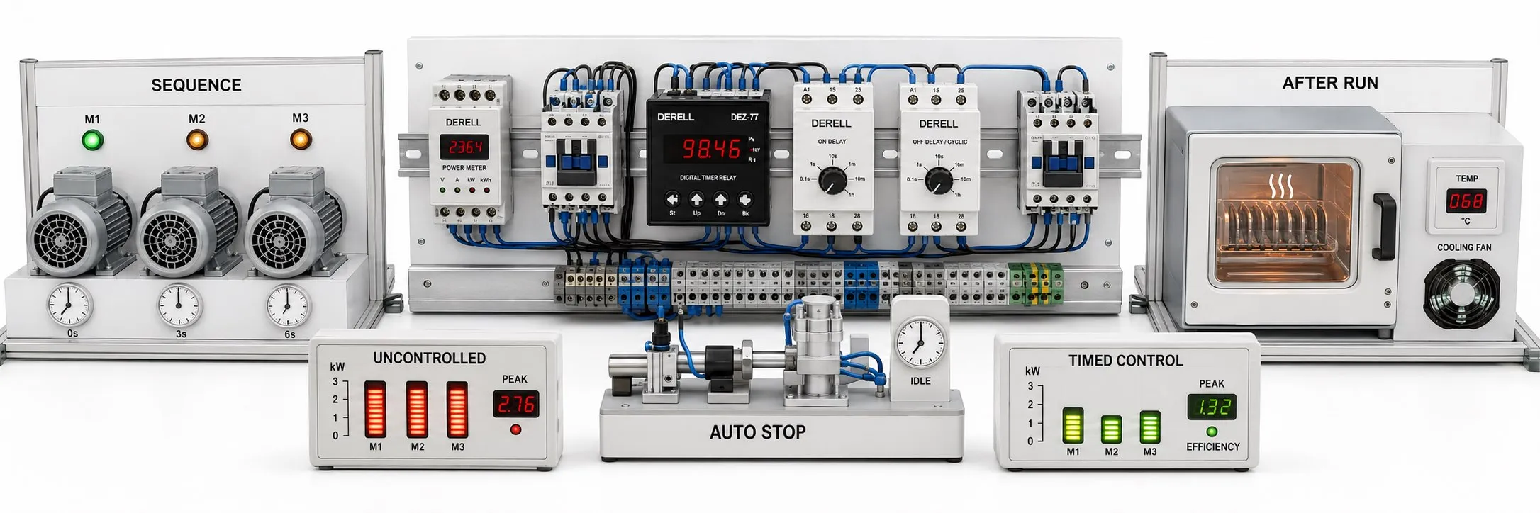
How can timer relays improve efficiency in automation systems?
A timer relay helps determine when an operation starts, how long it runs or when it stops after a command ends. Applied correctly, it can reduce unnecessary run time, inconsistent delays between operations and recurring timing errors. The benefit comes from timing that matches the process, rather than simply adding another device to the panel.
The different timer relay types used in motor, fan, valve and lighting circuits do not guarantee the same efficiency gains. A delay can organize production, while an unnecessarily long delay can reduce capacity. Measure the existing process before changing its timing.
1. Measure where the losses occur
Record cycle time, idle run time, fault-related downtime, reject rate and energy per good unit. A before-and-after comparison using the same product and similar operating conditions shows whether a change has helped.
For example, reducing the cycle of the operation that limits line output from 30 to 27 seconds increases theoretical continuous capacity from 120 to approximately 133 cycles per hour. This is an illustrative calculation; another bottleneck, quality loss or additional downtime can prevent a corresponding increase in actual production.
2. Combine operating sequences with real process conditions
On a transfer line, start the conveyor that receives the product first, then permit the feeding conveyor to run after operation has been confirmed. ON-delay timing can add an appropriate wait. However, an expired delay alone does not prove that the motor is turning or that the line is ready.
Where needed, combine timing with process feedback from a limit switch, speed signal, pressure or level measurement. A PLC can manage sequences involving many conditions. In the timing circuit, specify which command starts the timer and which condition permits the next step.
During a normal stop, ending product feed before allowing the transfer line to empty can reduce trapped material. If clearance time varies with loading and speed, use suitable detection or verified operating limits.
3. Reduce unnecessary operation while preserving required run-on
If an auxiliary fan must continue running after a process finishes, OFF-delay timing can preserve the required cooling or clearing period while preventing the fan from being left on indefinitely. A signal OFF-delay timer may need its supply to remain energized throughout the delay.
For shifts, weekends or daily schedules, consider an RTC timer or time switch. Combining demand information with an operating schedule can reduce unnecessary lighting and auxiliary equipment operation. Preserve the operating conditions required by essential ventilation and cooling functions.
Illustrative energy-saving calculation
Suppose an auxiliary fan draws a measured electrical input of 1.5 kW during unnecessary operation. Reducing that run time by 2 hours per day over 22 working days removes 1.5 × 2 × 22 = 66 kWh of load energy.
This is a hypothetical example; use actual electrical consumption rather than the motor's rated mechanical output. Verify the net saving through total system measurements that include control-device consumption and production conditions.
4. Apply timing appropriately to batches and cyclic operation
Timed mixing, holding or cleaning, after the required starting conditions are satisfied, can support consistency between products. A programmable timer may suit several timed steps; repeated switching can use a suitable cyclic or flasher function.
The same duration does not always produce the same quantity or quality. Opening a valve for 5 seconds does not guarantee the same liquid volume when pressure changes. In heating, temperature and load variation also matter. Measure and control the variables that determine product quality where necessary.
5. Stagger starts and choose the right motor control
Sequential starting can prevent several motors from starting together. Appropriate spacing can help reduce overlapping starting-current demands, provided actual acceleration times and loads are considered. A timer relay does not itself reduce an individual motor's starting current or mechanical shock.
Consider a suitable soft starter for soft starting, or a variable frequency drive (VFD) where speed and ramp control are required. A star-delta timer manages the changeover in that starting arrangement; it does not replace the necessary contactor interlocks.
6. Avoid creating new losses through excessive cycling
Frequent switching of pumps, compressors or contactor-controlled loads can increase the number of switching operations and maintenance demand. Set minimum run time, minimum off time and permitted starting frequency according to the equipment manufacturer's limits. One delay value cannot suit every system.
Select the timer's output stage for the actual load and use a contactor where appropriate. Understanding the different jobs of a relay and a contactor helps avoid overloading timer contacts. Assess contact life alongside load current and switching conditions.
7. Verify settings and power-restoration behavior
During selection and installation, check the supply, input type, time range and output capacity. Consider the adjustment convenience of an analog timer or the differences between a relay and a software timer where more operating conditions are involved. A digital display or RTC feature alone does not establish greater timing accuracy.
After configuring the time and function settings, test early command removal, retriggering, minimum reset time and restarting after power restoration. If problems occur, examine the supply, input, timing and load circuit separately during fault diagnosis. Record settings, the reason for the change and measured results in the panel documentation.
Distinguish safety functions from process timing
An ordinary timer relay must not replace a safety relay. Waiting for a set interval does not prove that motion has stopped, that a guard can safely open or that a hazard has disappeared. Safety-related delays require design and validation within an appropriate safety control architecture and risk assessment. A normal process-stop delay must not automatically be applied to emergency-stop behavior.
Technical references: OMRON timing functions · Reset, accuracy and contact life · Schneider Electric soft starting. Illustrative savings calculations do not replace measurements of the actual system.