
What is a Pulse Width Modulation (PWM) time relay?
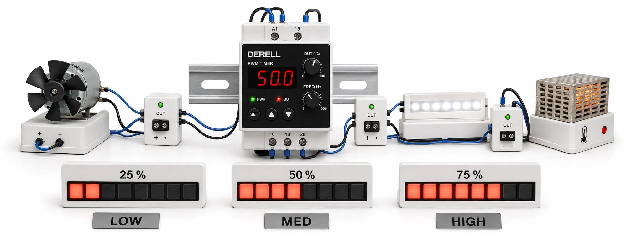
Distinguishing repeating on/off timing from fast power control
A pulse-generating time relay can provide a single timed output or repeat its output using defined on and off intervals, depending on the selected function. Repeating models let you set how long the load remains energized and de-energized. Catalogue terms may include asymmetric flasher, cyclic timer or pulse generator.
Pulse-width modulation, or PWM, controls a signal by changing pulse duration relative to its period. A timer relay can produce a similar time proportion at low frequency, but that does not automatically make it a high-frequency PWM power driver.
Editor's note: A product labelled PWM is not necessarily capable of directly driving a motor or LED load with fast pulses. First establish whether it has mechanical contacts, a transistor output, an AC SSR or a DC SSR. The timing function and the power-switching stage are separate specifications.
On time, off time, period and duty cycle
tON is the active output interval, while tOFF is the inactive interval. For a repeating cycle, T = tON + tOFF, f = 1 / T and D = tON / T × 100%. When T is expressed in seconds, frequency is in Hz. The duty cycle, D, describes the percentage of each cycle for which the output is active.
An output that is on for 2 seconds and off for 3 seconds has a 5-second period, a frequency of 0.2 Hz and a duty cycle of 40%. An output that is on for 1 ms and off for 1.5 ms also has a 40% duty cycle, but its frequency is 400 Hz. The time proportions match, while the required output hardware differs. The 400 Hz value is a calculation example only.
With fixed-frequency PWM, increasing tON requires reducing tOFF to preserve the period. On a timer with independently adjustable on and off intervals, changing just one interval can change both frequency and duty cycle. For contact outputs, connecting the load through NO rather than NC also changes which interval energizes the load.
Single pulses, repetition and starting behavior
A single-pulse function activates the output for a set duration after triggering. A repeating function continues alternating between on and off intervals while enabled. Some devices start with a pulse; others start with a pause. Triggering, retriggering, reset and retention after power loss depend on the model. Read the timing diagram together with the wiring diagram.
Mechanical contacts, transistor outputs and SSRs need different selection criteria
Mechanical relay output: Used for low-frequency timing and switching suitable loads. Contact life depends on switching frequency and load type. It is unsuitable for PWM at hundreds of Hz. A resistive-load current rating does not establish the same switching capability for a motor or coil load.
Transistor output: May support faster signal generation, but its maximum frequency, output current and voltage must be checked. A small signal output may not directly drive a high-power load. An application-specific MOSFET and driver stage may be needed.
SSR output: Solid-state relays have no mechanical contacts, but not every SSR supports fast PWM. A zero-cross AC SSR switches on according to the AC supply's zero crossing. It can support cycle or time-proportioning control of heaters, but cannot be treated as a kHz DC PWM switch. DC-output models also require checks of switching limits and heat dissipation.
Which approach fits the application?
Intermittent operation: Suitable valves, lubrication equipment or signalling loads can operate with repeating on and off intervals. For motor-driven loads, permitted starting frequency and protective arrangements also need assessment.
Heating: Operating a heater at a fixed duty cycle does not, by itself, maintain a constant temperature. Temperature feedback and a suitable controller are required. With PID temperature control or PLC-based control, the timing output must match the selected power-switching device.
DC motors and LEDs: True PWM applications use electronic drivers suited to the load. Repeatedly interrupting an AC motor's supply with a timer relay is not an appropriate speed-control method; use a motor drive suited to the application.
Selection and troubleshooting
Check supply voltage, on/off adjustment ranges, starting function, reset input and output type together. Do not assume every device supports a full 0% or 100% duty cycle. Verify minimum pulse and pause durations in the manufacturer's specifications.
If the output runs at unexpected intervals, first check the time units, selected function and trigger logic. An illuminated status LED does not establish that the load circuit is working correctly. Assess the supply, contact or electronic output, and load wiring together.
Related topics and application guides
Timing fundamentals: How time relays work, types of time relays, time relay versus timer and timer models and prices.
Repetition and programming: Flasher timers, multifunction timers, programmable timers and counting timers.
Other timing requirements: On-delay timers, off-delay timers, real-time clock timers and analog timers.
Selection, installation and troubleshooting: Selecting and installing a time relay, time relay settings, troubleshooting time relays and building a timing circuit.
Outputs and power control: Solid-state timers, how SSRs work, MOSFET fundamentals and PID temperature control.
Sources
Phoenix Contact: pulse, pause and repeating timer functions.
Phoenix Contact: example technical data for a relay-output timer.
Microchip: PWM, period and duty cycle.
Texas Instruments: motor interfaces and PWM frequencies.
Omron: SSR construction and power control methods; zero-cross operation.