
What is zero speed?
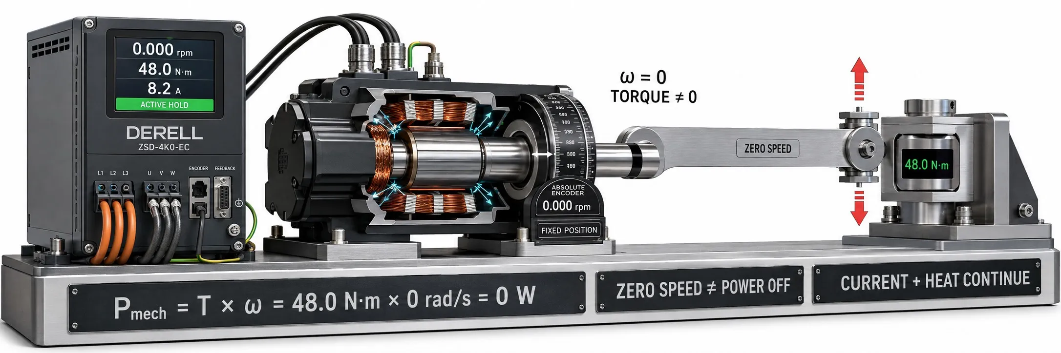
A stationary shaft can still have torque and current
Zero speed means that the monitored shaft or axis has no velocity. For a rotating motor, this means 0 rpm. It does not establish that the motor produces no torque, draws no current or is de-energized. Stopping movement, holding a load and removing electrical power are separate conditions.
A load may remain in place when a horizontal conveyor stops, while an axis subject to gravity may still require balancing torque at standstill. Zero-speed information must therefore be interpreted alongside the operating state of the motor and machine.
Editor's note: Torque does not have to be zero at zero speed. Mechanical power at a rotating shaft follows P = T × ω. Mechanical output power can be zero at standstill while the motor draws current and generates heat to hold a load. Understanding the difference between torque and power is essential when assessing standstill.
A zero command, 0 Hz and actual standstill are different
A zero speed reference means that the controller requests no movement. A displayed drive output frequency of 0 Hz describes an electrical output condition. Zero actual shaft speed describes the mechanical condition. Inertia, externally imposed movement or an inclined load can keep a motor rotating after a zero-speed command.
The reverse is also possible: suitable motor control can produce electromagnetic torque to balance a load while the shaft remains stationary. Displayed frequency, estimated speed and measured speed are different signals. When a digital output is assigned to zero-speed detection, check the manual to establish which signal it uses.
How does a servo produce torque at zero speed?
An actively controlled servo motor can hold a stationary axis against load torque. In position control, the drive regulates motor current according to the difference between commanded and feedback position. A stopped motor does not mean that the drive has stopped operating: the control system remains active during position holding.
Commands have different meanings in speed, torque and position control. A zero-speed command can coexist with nonzero torque; with a zero-torque command, external forces may move the axis. For example, a suitable motor balancing a 20 Nm load at standstill can produce 20 Nm while delivering 0 W of rotational mechanical power. Electrical consumption and losses must be assessed separately.
Can every AC drive hold a load at zero speed?
This depends on the motor type, control method, feedback and manufacturer's operating limits. Advanced vector control or direct torque control can provide different levels of performance at low speed and around standstill. A vector-control label alone does not guarantee indefinite, precise position holding under every load.
For sensorless operation in particular, near-zero-speed accuracy must be assessed against the algorithm and motor model. Applications requiring sustained load holding need verified continuous standstill torque and feedback requirements. Increasing a torque boost setting does not replace that assessment or a suitable braking arrangement.
What DC injection does and does not establish
DC injection braking applies direct current to the windings of compatible motor and drive systems to help slow rotation. It can reduce residual movement as an induction motor stops. This is different from the feedback-controlled active position holding used in a servo system.
DC injection does not guarantee load holding at zero speed. It should not be treated as a general-purpose static holding brake for an induction motor. Some drives have separate functions called DC hold; their purpose and limitations depend on the product manual. Holding action must not be assumed to continue after power is lost.
Higher injection current and longer injection times can increase the motor's thermal load. The method does not inherently save energy or guarantee longer motor life. Select the current, duration and repetition rate within the motor's thermal limits.
Braking resistors and mechanical brakes do different jobs
During deceleration, braking torque reduces the energy of motion. In a suitable drive system, energy returned by the motor can reach the DC link, where a brake chopper and braking resistor can help manage it. The resistor does not mechanically lock a stationary shaft.
A suitably designed mechanical holding brake holds a stationary load. Do not assume that a holding brake can act as a service brake to stop the rotating motor on every cycle. The brake command, release and application times and motor torque state must be coordinated; a motor-stopped bit alone does not define the complete brake sequence.
How does a drive generate its zero-speed signal?
Many devices detect standstill using a speed window and a confirmation time. As an illustrative example, an output could become active after absolute speed remains below 2 rpm for 200 ms. These are not recommended settings or universal standard limits; actual values depend on the machine's requirements.
Such a signal indicates that the relevant measurement has entered the defined window. It does not by itself prove exact mathematical zero, successful brake engagement or complete absence of load movement. Consider vibration around the threshold, measurement resolution and any configured hysteresis.
Limits of encoder feedback and pulse monitoring
Feedback can use an incremental or absolute encoder; resolver and encoder options must match the drive's supported interfaces. When monitoring is at the motor shaft, consider how the load could behave following a coupling or transmission failure. Choose the measurement point according to whether the required information concerns motor or load standstill.
Example: If the monitored input receives 60 pulses per revolution, rotation at 1 rpm produces only one pulse per second. Logic declaring standstill after 100 ms without a pulse could misinterpret that movement. Missing pulses may also indicate a broken cable or sensor failure. Absence of a signal alone is not dependable proof of standstill.
Keep zero speed separate from STO, SS1 and SOS
STO, Safe Torque Off, prevents torque production by the drive. If activated during motion, the motor may coast; external forces or gravity may move the load. STO therefore does not provide zero-speed load holding or controlled braking.
SS1 involves a controlled stop followed by STO; SS2 and SOS involve monitored standstill with control remaining active in a suitable system. An ordinary zero-speed relay or standard PLC bit is not automatically equivalent to these safety functions. The emergency-stop arrangement must be assessed against the machine's risks and chosen safety architecture.
STO does not provide electrical isolation. A stationary motor or active STO function does not establish that electrical parts are de-energized. Standstill monitoring, mechanical load safety and electrical isolation require separate assessment.
Account for heating during prolonged standstill
Active holding current produces winding losses. A motor relying on its own shaft-mounted fan may also lose cooling capability at low speed and standstill. For servo thermal management, check continuous standstill torque, current limits, ambient temperature and mounting conditions. Short-term peak torque is not a continuous holding rating.
Related drive control and braking topics
Compare vector control, flux vector control and direct torque control, DTC; distinguish command behaviour through speed control versus torque control; and explore stopping methods through DC braking.
Explore measurement and control components
Related topics include encoders for feedback, speed monitoring sensors for motion monitoring, PLC input and output modules for signal transfer, inductive sensors for pulse-target detection and overload relays for motor overload protection.
Find product groups on the variable frequency drives main page.
Sources
Beckhoff: standstill torque, standstill current and thermal terms
ABB: direct torque control and low-speed performance
Schneider Electric: DC injection and zero-speed holding limitations
Schneider Electric: motor heating during DC injection
Beckhoff: standstill window, timing and brake control sequence
Beckhoff: holding-brake operating limitations
Pilz: STO, SS1, SS2 and SOS functions
Danfoss: STO, external forces and electrical isolation limitations