
What is (DBU) dynamic brake unit?
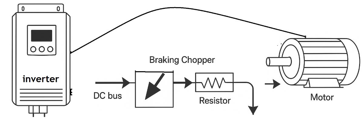
What is a braking chopper (DBU)? How does it work?
A braking chopper is an electronic switching circuit that controls the transfer of energy from a drive’s DC link to a braking resistor when the motor regenerates during braking. External units are also commonly described as a DBU — Dynamic Braking Unit. Correctly selected equipment helps limit DC-link overvoltage and support the required deceleration.
How does a braking chopper work?
During motoring, the variable frequency drive supplies electrical energy to the motor. A decelerating flywheel or a descending crane load can instead drive the motor mechanically. The motor then acts as a generator, returning electrical energy through the drive’s motor-side power stage to its DC link. This is regenerative operation.
The DC link is the drive’s intermediate DC circuit. Returned energy charges its capacitors and raises the DC-link voltage. A conventional diode-front-end drive cannot feed this energy back through its input to the mains. If insufficient energy is absorbed, the drive may trip on overvoltage or extend deceleration, depending on its control features.
When the chopper operates, a power switch, commonly an IGBT, switches the braking-resistor branch into conduction for short intervals. Current through the resistor converts energy into heat. Switching is governed by the unit’s voltage thresholds and control method. The drive and motor produce braking torque; the chopper and resistor provide a path for dissipating the returned energy.
Braking chopper, braking resistor and regenerative unit: what is the difference?
Braking chopper / DBU: The electronic circuit that switches current into the resistor. Braking resistor: The component that converts most of the transferred electrical energy into heat. These remain separate functions even when components are supplied together.
Regenerative unit or a suitable active front end (AFE): This can return braking energy to the mains. Energy recovery and cabinet heat become relevant when substantial braking energy is produced frequently or continuously. A chopper–resistor circuit alone cannot return energy to the mains.
DC injection braking: Direct current is applied to the motor windings to produce a braking effect, increasing motor heating. This is different from dissipating energy returned to the DC link in an external resistor.
Mechanical brake: This performs a separate function, such as holding a shaft or load. For example, holding a suspended crane load after power is removed cannot be entrusted solely to a braking chopper.
Which applications need an external DBU?
Fast stops of high-inertia loads require consideration of the rotational energy in a flywheel, centrifuge or large fan. A descending crane load or downhill conveyor can also drive the motor. Some applications regenerate without slowing down, so braking assessment involves more than the requested stopping time.
If the drive includes a braking chopper with sufficient capacity, the manufacturer’s specified compatible resistor may be all that is required. An external braking unit may be appropriate where no internal chopper is fitted or a suitable external solution is required. Compatibility is not universal: voltage class, accessible DC-link connections, control thresholds and the manufacturer’s permitted configuration must match.
Not every motor application requires a DBU. Natural load losses and a suitable deceleration time may be sufficient. However, extending the ramp does not necessarily solve the energy problem in a continuously overhauling load.
Which ratings matter when selecting a chopper and resistor?
Voltage and current: The drive and DBU must suit the application’s voltage class, and the chopper’s peak and continuous current limits must be respected. Chopper activation voltage varies between models. Motor nameplate power alone does not determine the correct chopper and resistor.
Resistance: Never select a resistance below the manufacturer’s stated minimum. During chopper conduction, approximately I = UDC / R and P = UDC2 / R. Lower resistance increases current at the same voltage; excessive resistance may provide insufficient braking power. This is the power during conduction, not the resistor’s continuous nameplate wattage.
Thermal capacity and duty cycle: Check continuous power, pulse energy per braking event, braking duration, repetition interval and cooling conditions together. Identical average power does not imply identical performance for different pulse durations. The chopper also has its own duty and ambient-temperature limits.
Why can the same motor require different braking resistors?
The energy removed from a rotating system is approximately E = ½ × J × (ω12 − ω22). Here, J is total inertia referred to the same shaft, and ω is angular speed in rad/s. Convert speed in rpm using ω = 2πn / 60. At unchanged inertia, doubling the starting speed quadruples the rotational energy removed in a stop to zero.
Lowering a crane load requires a separate assessment. The change in potential energy is approximately E = m × g × h, while mechanical power at constant lowering speed is related to P = m × g × v. Mechanical and electrical losses affect actual electrical braking power. Sustained load lowering has a different duty from an occasional motor stop.
What matters in wiring and thermal protection?
Terminal names are not universal. Markings such as P, N, DC+, DC−, PB or BR can have different functions across models. Connect an external DBU to the manufacturer-approved DC-link interface and the resistor to the specified braking circuit. A braking resistor must not be connected to motor terminals U/V/W or directly across DC+ and DC− while bypassing the chopper circuit.
Protective earth (PE) is not the return path for braking current. Protective bonding of metal enclosures is separate from the resistor power circuit. Cable type, length, conductor size, fusing and installation clearances must follow the drive, DBU and resistor manuals.
Braking resistors can reach high temperatures. Thermal switches or suitable temperature monitoring, ventilation and power removal under fault conditions must be designed together. A STOP command alone may not remove power from the resistor if the chopper transistor has failed short-circuit. The protection arrangement must include the isolation or switching devices specified by the manufacturer.
Installation and maintenance require qualified personnel, isolation of all energy sources and observance of the manufacturer’s capacitor-discharge time. Waiting alone is not proof of a safe condition; absence of voltage must be verified by an appropriate method.
Is a DBU a safe-stop or load-holding function?
Not by itself. A DBU supports the energy side of deceleration. A machine’s safe stopping arrangement depends on its motor, drive, controls, mechanical brake and risk assessment. STO (Safe Torque Off) prevents torque generation; it does not actively decelerate the motor or hold a suspended load. It also does not provide electrical isolation.
Reducing a crane’s stopping time and holding its load after stopping are different requirements. A correctly selected DBU and resistor do not remove motor current/torque limits or the mechanical system’s structural limits.
How should braking-related symptoms be interpreted?
Overvoltage during deceleration: Possible causes include an excessively short ramp, an inactive braking circuit, an open resistor or insufficient capacity. Supply voltage and drive control settings must also be considered; the fault code alone does not prove that the DBU has failed.
Excessive resistor temperature: Frequent braking, inadequate pulse or continuous capacity, poor cooling, an incorrect threshold or chopper failure may be involved. Bypassing thermal protection or simply lowering resistance is not a remedy.
Failure to stop within the set time: Assess torque/current limits, DC-link voltage control and the mechanical load. Installing a resistor with a higher wattage does not change all of these limits.
Common questions about braking choppers
Should the resistor heat up during every stop? Heating depends on the energy dissipated through it. A long ramp or low inertia may require little resistor operation; a lack of noticeable heating is not proof of a fault.
Does a higher resistor wattage produce stronger braking? With the same resistance and DC-link voltage, current during conduction is unchanged. A suitable higher power or pulse-energy rating can improve thermal capability; it does not determine braking torque by itself.
Does a DBU save electricity? A chopper–resistor circuit converts braking energy into heat. Returning energy to the mains requires an appropriate regenerative solution.
What information is needed for selection? Provide the full drive model and voltage class, motor nameplate, load type, operating speed, target stopping time, braking frequency and details of any existing resistor or DBU.
Technical references: ABB — Electrical braking; KEB — Braking resistor selection; KEB — Braking resistor protection; Schneider Electric — Braking techniques; Siemens — Safety Integrated / STO.