
What is DC breaking?
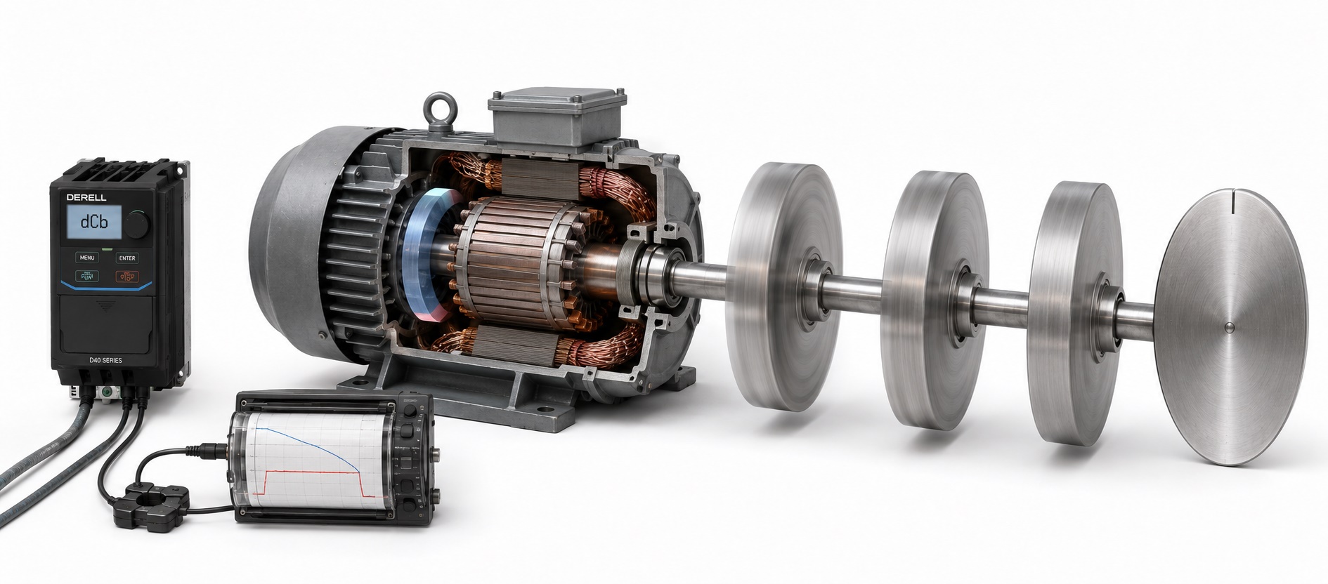
What is DC braking in an AC motor drive?
Bringing an AC motor to a stop is not always as simple as reducing the output frequency to zero. The motor and the machine still carry kinetic energy, and a high-inertia load may continue turning long after the drive starts to decelerate. Two common ways of dealing with this are DC injection braking and dynamic braking with a braking resistor.
The two methods may sound similar, but they handle the energy very differently. With DC injection, braking torque is produced inside the motor. With dynamic braking, the motor acts as a generator and sends energy back into the drive's DC bus. That excess energy can then be removed through a brake chopper and braking resistor.
On this page: DC injection · Dynamic braking · Braking resistor selection · Field applications
DC injection vs dynamic braking
The small interactive demo below shows the basic difference. In DC Injection mode, a stationary magnetic field is created in the motor. In Braking Resistor mode, the demo shows regenerative energy flowing back toward the DC bus and the resistor taking that energy away.
This demo is for educational purposes. Actual braking torque, DC-bus thresholds and permitted settings depend on the drive, motor and mechanical load.
How does DC injection braking work?
With DC injection braking, the drive stops producing its normal variable-frequency AC output and applies controlled DC current to the motor stator instead. This creates a stationary magnetic field. As the rotor continues to move through that field, a braking torque is produced against the direction of rotation.
The obvious advantage is that no external braking resistor is required for this method. The limitation is equally important: much of the braking energy ends up as heat inside the motor. Too much DC current, or applying it for too long, can raise the motor temperature very quickly.
This is why more DC current does not automatically mean better braking. On machinery that starts and stops repeatedly, both the injection level and the braking time have to be considered together with motor temperature.
How do dynamic braking and a braking resistor work?
Dynamic braking handles the energy in a completely different way. When the machine decelerates, the motor can briefly operate as a generator. The kinetic energy stored in the rotor and mechanical load is converted back into electrical energy and sent into the drive's DC bus.
As the DC-bus voltage rises, the drive's internal brake chopper, or an external DBU braking unit, switches a correctly selected braking resistor across the DC link. The regenerative energy is converted into heat in the resistor, helping to keep the DC-bus voltage within the drive's permitted range.
There is one point worth making very clearly: the braking resistor does not brake the motor directly. It gives the regenerative energy coming back from the motor somewhere to go.
Editor's note: Braking resistors are one of those components that look simple until you have to size one properly. A 5 kW motor does not automatically need a 5 kW resistor, and choosing a resistor by ohms alone is not enough either. Start with the drive manufacturer's permitted resistance range, then look at braking energy, stopping time, braking frequency and duty cycle. The wattage printed on the resistor is only one part of the calculation.
How should a braking resistor be selected?
The first figure to check is the drive manufacturer's minimum permitted braking resistance. Connecting a resistor below that value can force excessive current through the braking transistor or external chopper. This limit belongs to the drive design, which is why motor kW alone cannot determine the correct resistance.
The second part is peak braking power. How quickly the machine must stop, how much inertia is connected to the shaft, the change in speed and whether the load itself can drive the motor all affect the amount of regenerative energy produced.
The third part is average thermal load and duty cycle. A resistor that is energised for three seconds once every few minutes has a very different job from one that has to absorb braking energy every ten seconds throughout an entire shift.
So the useful question is not simply “How many watts should the resistor be?” A better question is: What resistance is permitted, how much peak energy must be absorbed, how long does each stop last and how often does it happen?
OtomasyonAVM carries braking resistors in several power classes for different drive and machine requirements. The main braking resistor section includes lower-power units as well as higher-power solutions for applications that brake more frequently or have considerably more stored mechanical energy.
Installation matters as much as calculation. A braking resistor is designed to turn electrical energy into heat. It therefore needs enough space to release that heat and should not be buried beside cable ducts, plastic components or heat-sensitive electronics. Surface temperature can become very high during repeated braking.
Is a brake chopper the same thing as a braking resistor?
No. The brake chopper is the electronic switching stage that monitors the DC bus and connects the resistor when braking energy causes the bus voltage to rise. The braking resistor is the power component that actually converts that electrical energy into heat.
Many small and medium-sized VFDs have the brake chopper built into the drive, with terminals provided for an external resistor. Larger drives may require a separate DBU braking unit. This is why seeing brake-resistor terminals on a drive should not automatically be interpreted as proof that every braking component is built in.
DC injection or braking resistor?
DC injection can be useful where the motor only needs a short final stopping action or where the braking demand is modest. It is simple, but repeated or aggressive use means more heat in the motor.
Dynamic braking with a resistor becomes much more useful on high-inertia machinery, frequent stop/start applications and machines that need short deceleration times. Where regeneration is almost continuous, converting all that energy into heat may no longer be the best approach; a regenerative drive or common DC-bus system may be worth considering.
The same issue appears frequently in servo systems. A positioning axis can accelerate and decelerate hundreds or thousands of times during normal operation, making regenerative-energy management part of the original machine design rather than an afterthought.
Common braking mistakes in the field
The first mistake is selecting a braking resistor by resistance alone. The ohm value may be correct while its thermal capacity or duty rating is nowhere near sufficient for the machine.
The second mistake is fitting a resistance lower than the drive manufacturer permits in an attempt to get “stronger braking”. The result can be excessive current through the brake chopper.
The third mistake is using an unnecessarily high DC-injection level or leaving DC injection active for too long. The motor may stop nicely while its windings are being heated far more than necessary.
The fourth mistake is installing a braking resistor in a closed corner of the panel with little airflow. The resistor is supposed to get hot; poor placement simply transfers that heat to everything around it.
The fifth mistake is treating every overvoltage trip as a parameter problem. On a high-inertia machine, the real question may be how much energy the moving mechanism is pushing back into the DC bus during deceleration.
A note from the field: When someone says, “The resistor is connected, so why am I still getting an overvoltage fault?”, the resistor itself is only the beginning of the diagnosis. Check the resistance value, thermal rating, duty cycle, brake-chopper operation and deceleration ramp together. Braking is a system; changing one component does not automatically fix the whole chain.
Monitoring braking through a PLC or HMI
If the drive makes parameters such as DC-bus voltage, overvoltage status, output current and fault history available over communications, they can be monitored by a PLC or HMI. On machines with frequent braking cycles, comparing DC-bus behaviour with the fault history can make it much easier to separate an electrical problem from a mechanical loading problem.
Related OtomasyonAVM topics
For a deeper look at the subject, continue with our braking resistor range, external braking units, braking resistor guide, VFD technical guide and servo systems.
Safety: Braking resistors can reach high surface temperatures, and dangerous voltage can remain on the DC link even after mains power has been removed. Always follow the drive manufacturer's discharge-time instructions and verify that the DC-bus voltage has fallen to a safe level before working on the equipment.