
IEC 60269
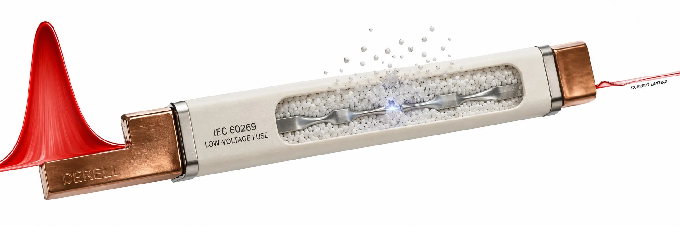
IEC 60269: Low-voltage fuses
IEC 60269 is an international standards series for fuses used in low-voltage electrical circuits. A fuse-link melts during an overcurrent to interrupt the circuit; an operated link must be replaced. The series defines requirements for different fuse systems and their performance. IEC 60269 is not a general standard covering all circuit breakers. Household-type circuit breakers are addressed separately by IEC 60898, while industrial circuit breakers fall within IEC 60947-2.
What voltage and breaking-capacity range does it cover?
IEC 60269-1:2024 covers enclosed current-limiting fuse-links. Its general scope includes power-frequency AC circuits with nominal voltages up to 1,000 V, DC circuits up to 1,500 V and rated breaking capacities of at least 6 kA. These scope limits do not mean every fuse can be used at 1,500 V DC. Check the selected product's voltage, AC/DC suitability and breaking-capacity ratings separately.
The parts of the IEC 60269 series
IEC 60269-1 sets out general requirements. IEC 60269-2 covers fuse systems intended for use by authorised persons, mainly in industrial applications; these include NH blade-contact, bolted and certain cylindrical systems. IEC 60269-3 concerns systems intended for operation by unskilled persons in household and similar applications; its 2024 edition applies only to gG fuses. This user classification does not authorise anyone to replace fuses inside an open electrical panel.
IEC 60269-4 addresses fuse-links for semiconductor protection. IEC TR 60269-5 is a technical report and application guide for low-voltage fuses. IEC 60269-6 addresses protection of photovoltaic strings and arrays, while IEC 60269-7 addresses batteries and battery systems. The DC fault conditions in these applications are not identical.
What do gG, aM, aR, gR and gPV mean?
The first letter describes the interrupting range: g indicates full-range capability; a indicates partial-range capability. The following letter or letters identify the application. gG provides general-purpose overload and short-circuit protection. aM provides short-circuit protection for motor circuits; it does not provide motor overload protection by itself. Coordinate it with a suitable overload relay or another motor overload protective device.
aR provides partial-range short-circuit protection for power semiconductors, whereas gR is a full-range semiconductor protection category. gPV is a full-range category for photovoltaic systems. gG, aM and aR fuses with the same ampere rating do not offer identical protection. For a variable frequency drive, follow the manufacturer's specified fuse category; input cable protection and protection of internal semiconductors may require different assessments.
How should ampere, voltage and kA markings be read?
On a hypothetical label marked 32 A / 500 V AC / 120 kA / gG, 32 A is rated current, 500 V AC is the stated AC voltage rating, 120 kA is breaking capacity under specified conditions and gG is the utilisation category. 120 kA is not the current carried during normal operation. A 32 A marking also does not mean instantaneous operation at 32.1 A: operating time depends on the time-current characteristic. The relationship between fuse rating and load therefore requires more than reading the ampere marking.
Current limitation, I²t and selectivity
At sufficiently high fault currents, a current-limiting fuse can reduce the peak current compared with the prospective short-circuit current. I²t = ∫i²dt is the time integral of current squared, expressed in A²s; it is not directly energy in joules. Pre-arcing I²t differs from total clearing I²t, which also includes the arcing period. For semiconductor protection, compare total clearing I²t with the device's withstand data under the relevant conditions. Assess selectivity using manufacturer curves and coordination tables; a higher-rated upstream fuse does not automatically guarantee that only the downstream fuse operates.
How is the standard applied in an installation?
Fuse selection considers normal load, starting pulses, ambient temperature, holder characteristics, cable cross-section and current-carrying capacity. The product's breaking capacity must suit the prospective short-circuit current at its installation point. The fuseholder must also match dimensions, contact requirements and permissible power dissipation. For combined devices such as fuse-switch-disconnectors, IEC 60947-3 may also apply. During replacement, isolate every supply, prevent re-energisation and verify the absence of voltage.
Publication information: Records checked on 9 October 2026 list IEC 60269-1:2024, IEC 60269-2:2013+AMD1:2016+AMD2:2024, IEC 60269-3:2024, IEC 60269-4:2024, IEC TR 60269-5:2014+AMD1:2020, IEC 60269-6:2010+AMD1:2021 and IEC 60269-7:2021. The June 2025 correction to Part 2 and November 2025 correction to Part 3 should also be accounted for in the relevant copies. Project documents should identify the applicable part, edition and amendments, not merely the series number.