
What are the control methods used in DC drives?
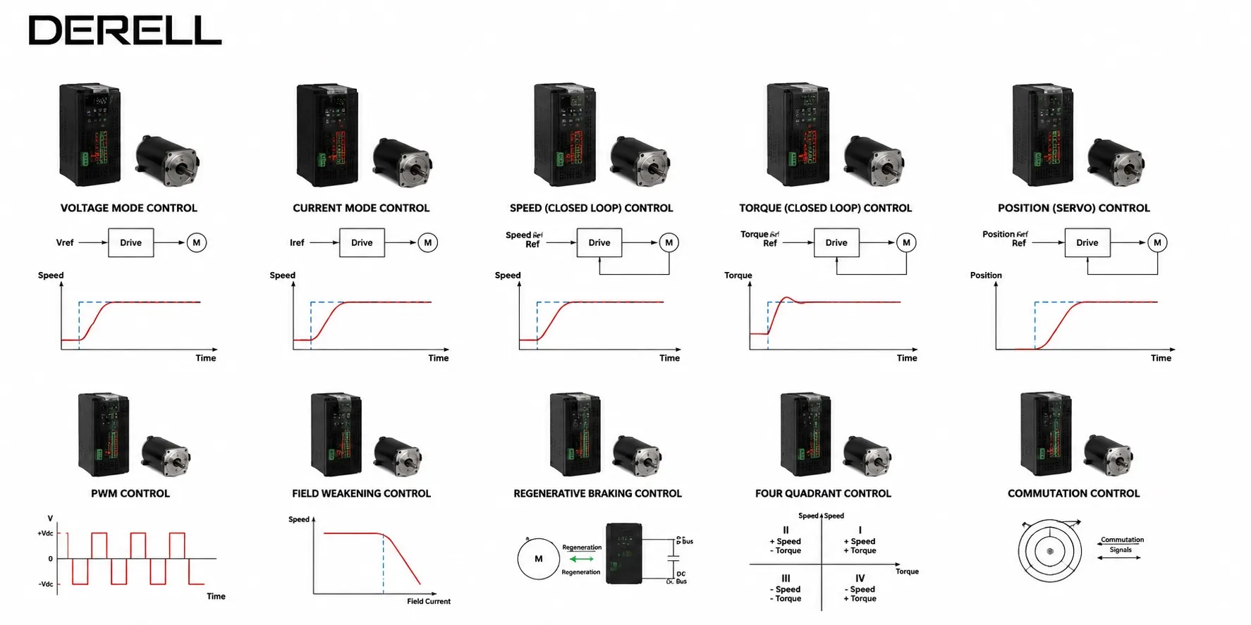
DC drive control methods: what the drive actually controls
A conveyor needs to hold its speed as material arrives. A winder needs to maintain tension as its roll grows. A reversing machine needs controlled braking before changing direction. These tasks may all use a DC drive, but they place different demands on its control system.
The main control variables are armature voltage, armature current and, where the motor permits it, field current. Speed and torque regulation build on those variables. PWM and thyristor firing control describe the power conversion stage; feedback describes how the drive checks its response; four-quadrant operation describes the available combinations of rotation and torque. These are complementary features, so several can operate together in one drive.
The following discussion concerns conventional brushed DC motors, especially permanent-magnet and separately excited designs. The motor construction determines which options are available. A brushless DC motor also needs electronic commutation and cannot be treated as a conventional two-terminal brushed motor.
Armature voltage sets the operating speed range
With approximately constant magnetic flux, increasing armature voltage raises the available speed. Under load, however, armature current produces a voltage drop across the winding resistance. A fixed voltage therefore does not guarantee a fixed speed. This distinction is central to understanding how a DC drive works.
A useful simplified motor model:
n ≈ (Va − IaRa) / (keΦ)
T = ktΦIa
Here, n is speed, Va armature voltage, Ia armature current, Ra armature resistance and Φ magnetic flux. The constants depend on the motor and units used. These steady-state relationships omit brush voltage drop and transient effects.
Below base speed, a motor operating at constant field can generally provide approximately constant torque capability up to its current limit. “Constant torque” describes the available operating envelope; it does not mean the shaft always delivers the same torque. Continuous low-speed duty may require separate ventilation. Checking motor and drive compatibility therefore involves thermal performance as well as electrical ratings.
PWM and thyristors provide two ways to control motor voltage
A PWM power stage switches the supply rapidly and varies the duty cycle to adjust average motor voltage. For an ideal, simple one-quadrant chopper, Vaverage ≈ D × VDC. A 24 V supply at 50% duty therefore gives approximately 12 V average output. It does not promise 50% of rated motor speed. Load and internal voltage drops still matter, and other H-bridge switching schemes require a different duty-cycle relationship.
Many industrial line-fed DC drives use phase-controlled thyristor bridges instead. Their firing angle controls the average armature voltage. When comparing DC drive technologies, keep the power stage separate from the regulation strategy: either approach can support closed-loop current and speed control when appropriately designed.
Speed control responds to a changing load
A speed controller compares the commanded speed with a measured or estimated value. In a typical industrial arrangement, the outer speed loop generates a current demand, and the faster inner current loop regulates armature current. PI regulation, part of the wider PID control family, is commonly used; derivative action is not automatically required.
Consider a conveyor running at 1,000 rpm. Adding material increases the required shaft torque. As speed begins to fall, the controller requests more current to restore it, provided the drive still has sufficient voltage and current available. Once an operating limit is reached, increasing controller gain cannot create additional motor capacity.
An encoder or tachogenerator provides information from the rotating shaft. Other drives estimate speed using armature voltage and compensation for internal voltage drop. These feedback arrangements offer different performance, particularly at low speed. No encoder does not necessarily mean no feedback control. The quality of the estimate and the tuning both influence the system's dynamic response.
Torque control regulates effort rather than speed
At constant flux, electromagnetic torque is approximately proportional to armature current. A drive can therefore regulate torque through its current loop. A current limit in speed mode is not the same as torque mode. The former caps the effort available to maintain speed; the latter makes current or torque the primary demand.
This is particularly useful in winding and unwinding applications, but constant torque alone will not maintain constant web tension as roll diameter changes. Ignoring losses and acceleration, the roll requires T = F × r. A 100 N web force needs 10 N·m at a 0.10 m radius and 20 N·m at a 0.20 m radius. Those are roll-shaft values; gearbox ratio and efficiency must be included when calculating motor torque.
Diameter estimation or a tension loop using suitable process sensors may therefore be needed. A torque-controlled axis also needs an appropriate speed limit: if the web breaks, the load can disappear while the torque command remains, causing rapid acceleration.
Field weakening extends speed at the expense of torque
On a separately excited motor, the drive can reduce field excitation after reaching the permitted armature voltage. This allows operation above base speed. Reducing flux also reduces the torque available at a given armature current. Within the permitted operating envelope, the result is an approximately constant-power region.
For an ideal constant-power example, doubling speed halves available torque. Whether that speed is permissible depends on the motor's mechanical and commutation limits. Conventional permanent-magnet brushed motors have no adjustable field winding, so this method is unavailable in the same form. Intentional field weakening must also be distinguished from an uncontrolled loss of field.
Four-quadrant operation adds controlled braking in both directions
Four-quadrant capability means the drive system can produce motoring and braking torque in either direction of rotation. During forward braking, for example, shaft speed remains forward while torque acts against that motion. Simply being able to reverse the motor does not establish four-quadrant capability.
The destination of braking energy is a separate design question. Energy returned from the motor may enter a DC bus, a suitable battery, a braking resistor or, with the necessary converter arrangement, the AC supply. Four-quadrant motor operation does not by itself guarantee regeneration into the mains. The complete energy path must be considered when assessing drive efficiency and braking performance.
A PLC supplies the demand; the drive closes the fast loops
A potentiometer, analog input or communication network can provide the operating reference. With PLC integration, a machine controller can coordinate speed demands, torque commands and operating sequences. The drive usually handles the fast current and speed regulation internally.
The command source does not define the control mode. An analog signal could represent speed in one configuration and torque in another. Its scaling, direction convention and response to signal loss must match the machine's intended behaviour.
Match the control structure to the job
For steady conveyor speed: use speed regulation with feedback suited to the required accuracy. For controlled web tension: combine torque regulation with roll geometry and, where needed, measured tension. For operation above base speed: confirm that both the motor and drive support field weakening. For frequent braking or reversing: check the operating quadrants and where the braking energy will go.
A sound DC drive selection considers armature and field ratings, continuous current, overload duty, cooling and the full speed range. Matching the power rating alone is insufficient. Feedback hardware and other supporting components must also suit the chosen control arrangement.