
Extra components with DC drives?
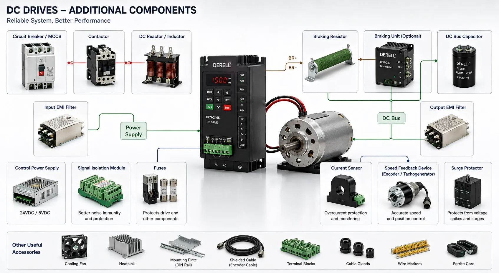
What additional components are used with DC drives?
A working DC motor installation involves more than the drive itself. Power must reach the motor through suitable protective equipment, control signals must be compatible, and heat must leave the enclosure. Depending on the machine, the installation may also need feedback sensors, a field supply, braking equipment or a communication interface.
The useful question is therefore not “Which accessories should every drive have?” but “Which functions does this particular system need?” Start with the motor and the type of DC drive. Then identify what is already built in and what must be provided externally.
Identify the power supplies first
A separately excited DC motor has an armature circuit and a field circuit. Its field winding requires an excitation supply, which may be integrated into the drive or supplied by a separate field controller. A permanent-magnet motor has no field winding, so it does not need this equipment.
Small PWM drives commonly operate from an external DC source. That source must suit the drive voltage and the current demanded during acceleration and load changes. Its ability to handle energy returned during deceleration also matters: many ordinary power supplies can deliver power but cannot absorb it.
A separate 24 V supply may power sensors, control circuits and relay coils. Motor power, field excitation and auxiliary control power are different duties, even when some of them are packaged inside the same drive.
Provide coordinated protection and switching
Fuses, circuit breakers and disconnecting devices serve different purposes. A breaker selected to protect wiring does not automatically provide adequate protection for the drive’s power semiconductors. Some converters require manufacturer-specified semiconductor fuses, with the complete arrangement coordinated for the available fault current.
Contactors may be used in the power circuit, while auxiliary relays exchange permissive and status signals. Switching DC requires suitable DC ratings; an AC rating alone is insufficient. Any contactor between the drive and motor must operate according to the approved drive sequence. Routine speed control should be handled through the drive’s commands, rather than repeated power switching.
These external devices work alongside the drive’s internal protection functions. Neither group should be selected in isolation from the other.
Treat reactors and interference filters as separate items
A line or commutation reactor addresses the electrical conditions at the input of a converter, particularly in thyristor-based systems. An armature smoothing reactor addresses current ripple in the motor circuit. Their positions and design objectives differ.
An EMC filter is intended to control high-frequency interference. It is not a universal remedy for low-frequency harmonics or irregular motor current. Likewise, an output filter designed for an AC variable-frequency drive should not be assumed suitable for a DC converter.
Good cable routing, shielding and grounding remain part of the installation. Adding a filter cannot compensate for every wiring problem.
Decide where braking energy will go
When a moving load drives the motor during deceleration, energy must be handled somewhere. A regenerative drive may return it to the mains. Another system may dissipate it through an engineered dynamic-braking circuit. The appropriate arrangement depends on the converter and the machine’s stopping requirements.
A braking resistor is therefore an application-dependent component, not a standard attachment for every DC drive. Resistance, energy capacity, cooling and switching equipment must suit the intended duty. A resistor should not be connected arbitrarily across the motor or drive terminals.
A mechanical holding brake has another job: keeping a load stationary when required. Electrical deceleration and load holding should be considered separately, especially on vertical machinery.
Add feedback where the process needs it
A basic application may operate without an external speed sensor. Tighter speed regulation under changing load can justify an encoder or tachogenerator. Encoder pulses support speed measurement and, with suitable control hardware, position tracking. A tachogenerator produces a voltage related to rotational speed; it is different from a handheld instrument used for occasional speed checks.
Check the supported feedback interfaces before choosing a sensor. Supply voltage, signal format, speed range and mechanical coupling all matter. An accurate sensor connected to the wrong interface will not produce a reliable control system.
Signal conditioners can match a controller’s output to the drive’s analog input. Where electrical separation is needed, an isolating conditioner can also help manage unwanted current paths between control circuits. Signal conversion and galvanic isolation are distinct features, so check which ones the device actually provides.
Connect the drive to the machine controller
A PLC can coordinate the drive with sensors, valves and other motors. An HMI gives the operator access to permitted settings, operating values and fault messages. Neither is essential for every standalone drive application, and neither directly replaces the drive’s power stage.
PLC integration can use wired I/O or a supported industrial network. A protocol such as Modbus RTU may require an optional interface module. A gateway can be useful when the two devices support different networks, provided the required data and control behavior can be mapped correctly.
Ordinary control commands and display functions should not be mistaken for certified machine safety functions.
Account for heat and supply isolation
Cabinet fans, filtered ventilation or enclosure cooling remove the heat generated by the drive and nearby equipment. The motor may need its own independent blower when prolonged low-speed operation reduces the airflow from a shaft-mounted fan. A winding-mounted PTC sensor, connected to a compatible input or protection relay, can support thermal monitoring.
A transformer may be needed for voltage matching or galvanic isolation, depending on the supply and converter arrangement. It is not compulsory in every installation. An autotransformer does not provide galvanic isolation, and an isolation transformer does not remove the need for correctly designed protection and protective grounding.
Build the equipment list around the job
For a small permanent-magnet motor, the practical package might consist of a compatible DC source, PWM controller, protective devices and a speed reference. A production winder may instead need a wound-field motor, field controller, encoder, PLC interface and regenerative converter. The difference comes from the required operating behavior, not simply from the motor’s power rating.
Before purchasing accessories, compare the proposed arrangement with the drive’s connection diagram and option list. This is also a useful stage to consider access for inspection, spare parts and future maintenance.