
How energy-efficient are DC drives?
How energy-efficient are DC drives?
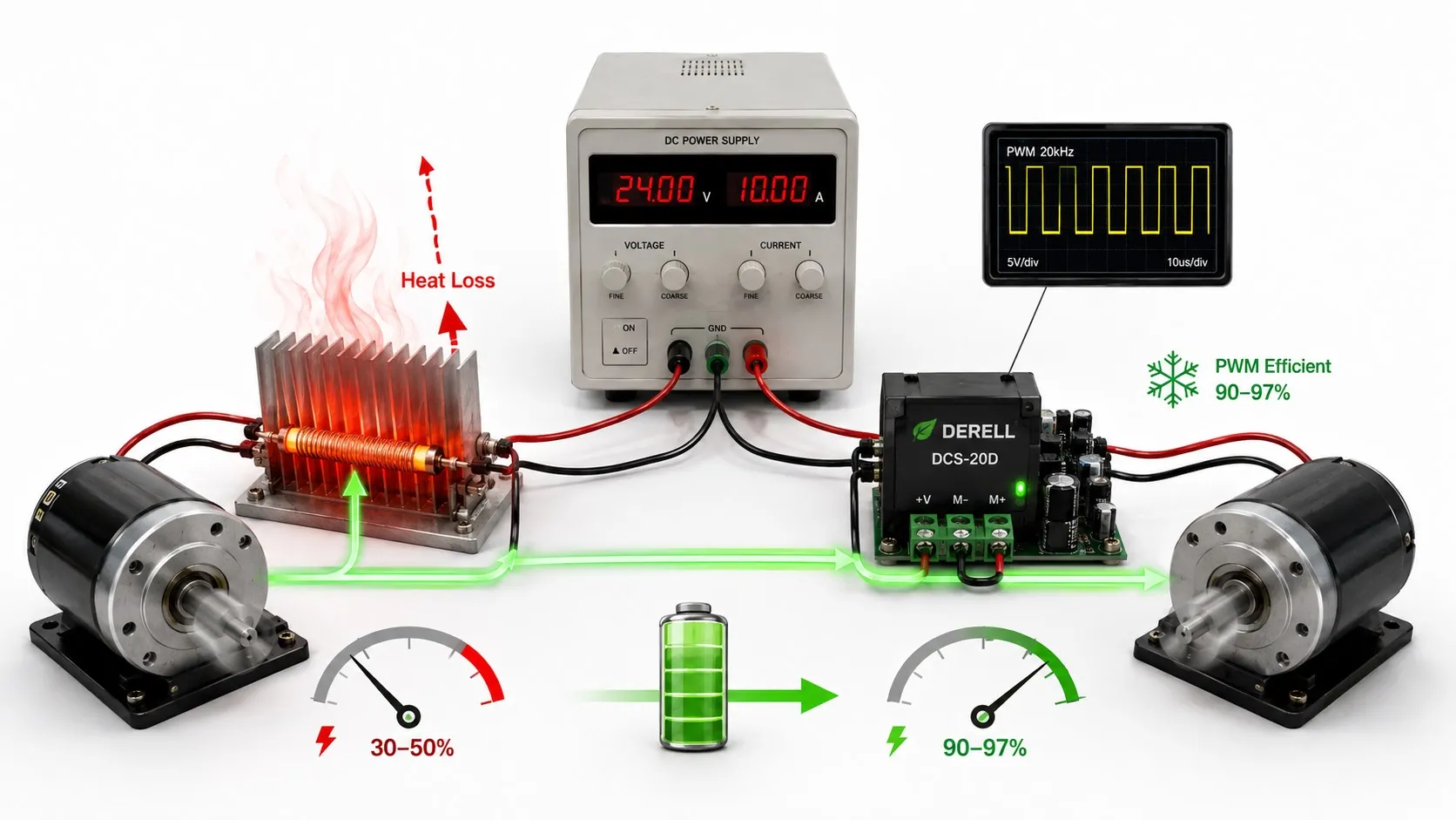
There is no universal efficiency percentage for DC drives, and no reliable rule that every DC installation consumes more energy than an AC alternative. The answer depends on what is included in the measurement and how the machine operates. Converter losses, motor losses, cooling and the production duty all contribute.
A useful comparison between a DC drive, an AC motor with a VFD, and a servo system starts with the same mechanical task. Matching nameplate power alone is not enough: speed, torque, operating hours and output quality must also be comparable.
Choose the measurement boundary before quoting efficiency
Converter efficiency describes the electrical power transferred through the drive within a defined boundary. Motor efficiency compares mechanical shaft output with the motor’s total electrical input. System efficiency includes the additional equipment inside the chosen assessment boundary.
These distinctions matter for a separately excited DC motor. Measuring only armature power leaves out the field supply. Measuring only the converter may also omit an independent motor blower or cabinet cooling equipment.
For illustration, suppose the complete installation draws 10 kW, including field excitation and auxiliaries, while the motor shaft delivers 8.5 kW. Efficiency across that boundary is 8.5 / 10 × 100 = 85%. This is a calculation example, not a typical rating assigned to all DC equipment.
Identify where the losses occur
Electrical winding losses: Current produces heat in the armature and, where fitted, the field winding. Copper loss follows approximately P = I²R. Doubling current quadruples this loss if resistance remains unchanged. With ripple current, the RMS value matters for heating.
Brush and mechanical losses: Brush-contact voltage drop, brush friction, bearings and ventilation contribute to motor losses. These belong to the brushed motor rather than the electronic converter. Appropriate motor maintenance helps keep the installation operating as intended.
Magnetic and converter losses: The motor has magnetic losses, while power semiconductors and control electronics dissipate energy. A thyristor converter and a PWM drive have different loss characteristics. Reactors, transformers and cooling equipment can add further consumption.
The relevant supporting components should therefore be included consistently when comparing installations.
Why low speed and light load need separate attention
At light load, some losses decrease while others remain relatively steady. Control electronics, excitation and cooling may consume a larger share of the total input as useful output falls. Actual loss data over the working speed-torque range are more informative than a single peak-efficiency figure.
Low speed does not necessarily mean low current. With approximately constant flux, producing the same torque requires approximately the same armature current. Mechanical output falls with speed, but copper losses may remain substantial.
This also matters for a servo motor holding a stationary load. It can consume electrical power while delivering zero mechanical power because there is no movement. For that duty, holding requirements and energy per operating cycle are more useful than an isolated shaft-efficiency percentage.
Process savings can matter more than converter losses
Improving conversion efficiency and reducing the energy required by a process are related but different opportunities. A machine operating faster than necessary may waste energy even if its motor and converter are efficient.
Suitable centrifugal pump and fan systems can reduce their required shaft power substantially when speed is matched to demand. This is an important application of VFD energy savings. The same speed-power relationship should not be assumed for constant-torque conveyors or lifting mechanisms.
For a DC machine, appropriate speed references and torque control can also help match operation to the process. A vector-controlled AC drive or servo system is not automatically energy-saving merely because it offers advanced control.
Recover braking energy when the duty justifies it
During deceleration, or when an external load drives the motor, mechanical energy can be converted back into electrical energy. A compatible regenerative DC system can return it to the mains or another supply capable of accepting it.
A braking resistor takes a different approach: it dissipates braking energy as heat. Replacing resistor braking with an appropriate regenerative arrangement can reduce net consumption when braking energy is significant.
Recovery is limited by the energy actually available and by conversion losses. A machine that motors continuously and rarely decelerates may offer little recoverable energy. Repeated acceleration-deceleration cycles or overhauling loads can provide a stronger opportunity.
Regeneration is also available in suitable AC inverter systems. Supported common-DC-bus servo arrangements may share energy between axes. Sharing a DC bus does not, by itself, mean that the installation can export energy to the mains; the upstream converter must support that function.
Do not confuse efficiency with power factor
Efficiency compares useful output with input. Power factor compares active power with apparent power on the AC supply side. Thyristor firing angle and input-current distortion can influence power factor, while harmonic currents may increase losses in upstream cables and transformers.
A lower input-current reading does not necessarily represent the same percentage reduction in energy use. Measure active power and accumulated kilowatt-hours. On a DC output with significant ripple, multiplying average voltage by average current may also fail to represent true average power.
The measuring equipment must suit the waveform, and the assessment should include the relevant supply and auxiliary circuits.
Compare DC, VFD and servo solutions over the actual duty
A suitable AC motor and VFD may offer an attractive combination of energy performance and reduced brush-related maintenance in a new installation. In an existing plant, retaining a healthy DC motor and replacing its converter may offer a better overall result. The decision should follow measured operation and appropriate drive selection.
For precision machinery, motion profiles and mechanical sizing also affect energy use. Unnecessary acceleration or oscillation can demand additional current. Suitable servo gain tuning and speed-loop adjustment support controlled motion, but they do not establish a universal savings percentage.
The comparison should cover the working cycle, including production, waiting, holding and braking, rather than only the rated operating point.
Turn measured power into an energy comparison
Keep production quantity and quality comparable. A machine consuming less because it produces fewer acceptable parts has not necessarily become more efficient. Depending on the process, useful indicators include kWh per product, kWh per tonne or energy per completed cycle.
As an illustrative calculation, reducing average total input power from 11 kW to 10 kW for the same work saves 1 kW × 4,000 hours = 4,000 kWh per year. For changing loads, account for the power and duration of each operating segment. Regenerative operation requires measurement that distinguishes energy drawn from energy returned.
A PLC or monitoring system can record production counts and operating time. Electrical consumption should be obtained from suitable power-measurement equipment, with a clearly stated boundary covering field excitation and auxiliary loads.