
VFDs input Filter
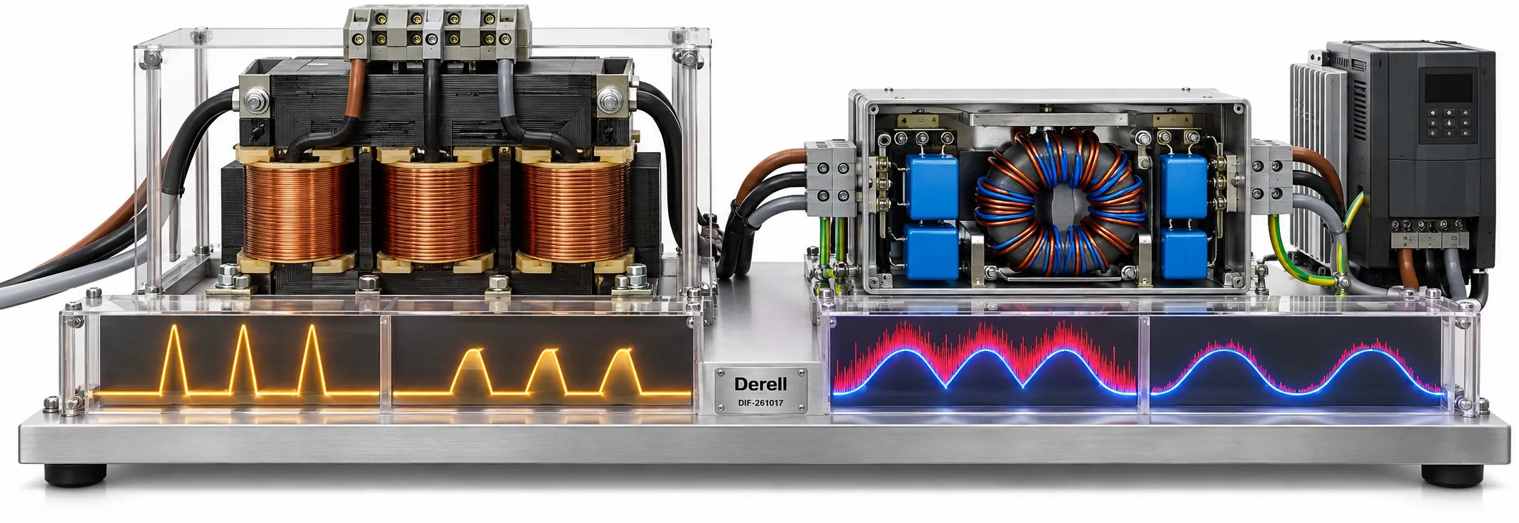
Match the input equipment to the disturbance
A drive installation can need an EMC filter, an input reactor, or both. The filter attenuates high frequency noise travelling through the supply wiring. A reactor adds inductance to the supply circuit, limiting rapid current changes and helping reduce input current distortion in suitable applications. Neither device regulates the mains voltage or provides complete protection against every surge.
Why one drive creates more than one problem
A conventional six pulse variable frequency drive draws non-sinusoidal current through its input rectifier. Its output IGBTs produce fast voltage transitions, with interference influenced by the switching frequency and the installation. Low order mains harmonics and high frequency switching noise require different remedies. An harmonic filter addresses a different problem from an EMI filter or RFI filter.
EMC filtering: Inductive and capacitive components attenuate conducted disturbances over specified frequency ranges. Performance against common mode and differential mode noise depends on the filter design. Radiation from motor cables also calls for suitable shielding, cable routing and enclosure bonding. An input filter alone does not establish compliance for the complete drive system.
Line reactors: A series reactor opposes rapid changes in current. It can reduce rectifier current peaks and the effects of certain supply disturbances. A DC bus choke can also help reduce harmonics, but connects at a different point in the drive circuit. Check the existing internal choke before adding external impedance.
Keep supply problems separate from motor problems
Use the electromagnetic filter family to investigate noise conducted back towards the supply. For steep voltage edges at the motor or long cable effects, investigate an output filter, a du/dt filter or an approved sine filter. An output reactor and a zero phase reactor serve other specific purposes. The wiring diagram and the drive manufacturer's compatibility instructions determine where each device belongs.
Specify the filter by the installation
For an EMC filter, identify the exact drive model, phase configuration, supply voltage, rated input current, ambient temperature and required EMC category. Select a combination supported by the manufacturer. Rated power alone is insufficient: motor cable construction, cable length and switching frequency can affect the compliance conditions.
For an input reactor, check current, voltage, supply frequency, inductance or percentage impedance, overload duty and acceptable voltage drop. Adding more impedance can reduce the voltage available to the drive. Special variable-inductance designs, often called swinging chokes, exist, but this behaviour is not a general property of every line reactor. Harmonic improvement must be assessed for the actual drive, load and supply.
Environment categories do not set a universal cable limit
In IEC/EN 61800-3, the first environment includes premises directly connected to a public low voltage network that also supplies residential buildings. The second environment covers premises outside that definition. Drive categories C1, C2, C3 and C4 are assessed separately; calling these environments “two interference levels” obscures the distinction.
There is no blanket 30 m or 100 m motor cable allowance. Use the manufacturer's limits for the specified drive, filter, cable and switching frequency. Likewise, no single harmonic reduction percentage applies to all reactors. THDi expresses harmonic current relative to the fundamental current: a higher percentage at light load does not automatically mean more harmonic current in amperes.
A suitable filter still needs suitable installation
Follow the specified conductive mounting arrangement, keep filter-to-drive wiring short and separate the supply side wiring from the noisy side. Protective earth continuity and appropriate shield bonding are essential. Y capacitors can contribute to protective conductor current, so residual current protection must suit the complete installation and the drive instructions. Check filter compatibility on an IT supply; never disconnect protective earth to cure interference or unwanted tripping. Stored charge can remain after isolation: follow the manufacturer's discharge time and verify absence of voltage before work.
When investigating drive fault codes, record the operating condition as well as the alarm. The VFD prices section can help compare equipment, but compatibility and electrical ratings determine the filter selection.
References
ABB — EMC installation guide · Schneider Electric — AC reactors and DC chokes · ABB — Harmonics and swinging chokes · Schneider Electric — Drive leakage currents · TDK — EMC filter application notes · IEC 61800-3:2022/COR1:2025