
What is Electromagnetic filters?
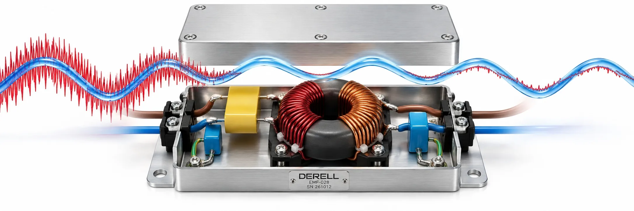
Let the useful signal through, reduce the interference
An electromagnetic filter is a circuit or component network that reduces unwanted electrical noise on a power or signal connection. The design must preserve the required energy or information while attenuating unwanted frequency components. Its effectiveness depends on the noise path it is designed to address; a line filter cannot remove every electromagnetic field around a machine.
The terms EMC filter, EMI filter and RFI filter often overlap. EMC concerns compatibility, EMI refers to interference, and RFI concerns radio-frequency interference. The labels alone do not identify three different circuit designs.
Start with the source and the coupling path
A variable frequency drive produces fast switching edges through PWM. Switch-mode power supplies and switching relays can also introduce disturbances. Incorrect PLC input states, unstable sensor readings or lost encoder counts may be symptoms. Timing that matches another device switching is a useful clue, not a complete diagnosis.
An LC network combines inductors and capacitors. Differential-mode noise circulates between conductors. Common-mode noise travels in the same direction on conductors and may return through chassis or stray capacitance. Common-mode chokes and X/Y capacitors address these paths. X capacitors connect across lines; Y capacitors may connect lines to earth or chassis in a suitable design.
Watch the small, rapid variations
The blue dashed curve is the useful supply reference. The red curve shows supply and interference together. On the right, the slower waveform remains while the rapid variations shrink. Attenuation does not mean complete removal. Start the paired scanning lines to compare matching positions. This is a schematic illustration, not a product measurement or a wiring diagram.
Cutoff is not a suppression-strength control. Raising a low-pass filter's cutoff generally allows more of the same high-frequency disturbance through. Lowering it too far can also attenuate useful content. Real EMC products are assessed using attenuation versus frequency, not an arbitrary cutoff percentage.
Select by the connection being filtered
AC mains filters serve single-phase or three-phase supply connections. DC line filters target switching noise on DC supplies. Signal and data-line filters must preserve the bandwidth needed for communication. Ferrite components provide frequency-dependent suppression, but a ferrite fitted around a cable is not automatically a substitute for a complete LC filter.
A harmonic filter addresses power-quality problems such as lower-order supply-current harmonics. dv/dt and sine-wave filters operate between the inverter and motor. Mains input filters and motor output filters are not interchangeable.
Installation can make or break the result
Bundling input and output wiring together can let noise couple around the filter. Use short connections, broad conductive case bonding and proper protective earthing. Check supply voltage, phase arrangement, equipment input current, temperature and leakage current together. Y capacitors can produce capacitive earth leakage during normal operation, which must be considered when selecting residual-current protection.
Related reading
References
TDK: Switching noise and filter principles; TDK Electronics: EMC filters and installation; Texas Instruments: Low-pass filter response; Danfoss: Harmonic and motor output filters.