
What is EMC emission?
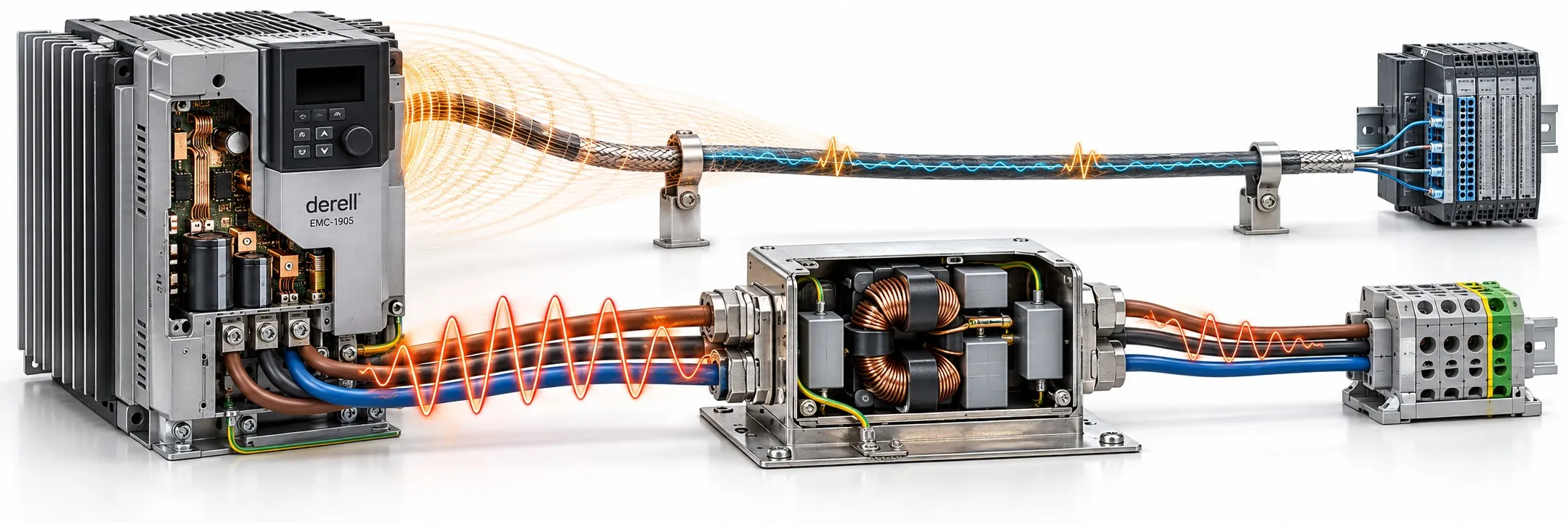
Where switching noise goes after it leaves a device
Electromagnetic emissions are disturbances a working device introduces into its surroundings or connected conductors. A variable frequency drive can run its motor correctly while disturbing a nearby measurement circuit. Producing emissions does not necessarily cause interference: a coupling path must carry sufficient disturbance to a susceptible circuit.
Emission describes what equipment sends out; immunity describes its ability to keep working when disturbances arrive. A quiet device is not automatically a resilient one. When electromagnetic noise reaches another circuit, the result may be a false trigger, a measurement error or lost communication. Physical damage is only one possible outcome.
Follow the cable, then examine the fields
Conducted emissions travel through supply wiring, signal connections, chassis and other conductive paths. Noise from a drive can therefore reach equipment sharing its supply. Radiated emissions involve electromagnetic fields around the equipment; cables and enclosure openings can contribute to radiation. Nearby wiring can also pick up disturbances through capacitive or inductive coupling. Local field coupling should not all be treated as far-field radio-wave propagation.
PWM switching and switching regulators create rapid voltage and current transitions. dv/dt describes voltage slew rate; di/dt describes current slew rate. Shorter transition times can strengthen high-frequency spectral content. Changing the switching frequency moves spectral components, but does not guarantee that every measured peak increases. Ringing, operating conditions, return paths and cable geometry also matter.
Different paths call for different countermeasures
Select Start to trace the paths. On the upper route, smaller dots after the EMI filter represent attenuated conducted disturbance. The lower example shows a bonded metal enclosure as a measure that can reduce field coupling to surrounding circuits. Neither route implies complete elimination. Dot size is not a dB reading. With reduced motion enabled, the explanation remains static.
A line EMC filter targets high-frequency conducted noise and serves a different purpose from a harmonic filter. An output filter may address motor-side voltage transitions or other disturbances, depending on its type. Choosing an electromagnetic filter requires more than matching its current rating: consider the noise frequencies, common-mode and differential-mode behavior, and installation instructions.
Shield termination, enclosure continuity and separation of power and signal wiring influence field coupling. Applicable drive installations call for 360-degree shield termination with low high-frequency impedance. Protective earthing and effective high-frequency bonding have related but distinct purposes; a protective earth connection alone does not demonstrate EMC performance. Routing the filter's input and output wiring together can allow noise to couple around it.
Read the test conditions with the result
An emissions result is not a universal percentage. It is a frequency-dependent measurement obtained with specified equipment, detectors and operating conditions. For supply-port conducted testing, a LISN establishes a defined impedance; voltage results are commonly expressed in dBµV. An antenna-based electric-field measurement uses dBµV/m. The units describe different quantities. The applicable product standard determines the test band, limits and setup. Documents in the EN 61000 and IEC 61000 families have different roles; not every part defines emission limits.