
What is Zero phase reactors?
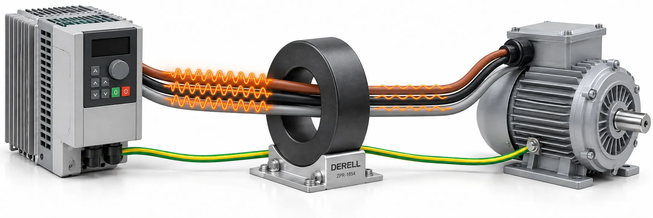
A shared core that treats motor current and noise differently
A zero-phase reactor is a passive magnetic component used to reduce high-frequency common-mode current. Several power conductors pass through one shared core. In variable-frequency drive and servo motor installations, this can reduce interference carried by, and radiated from, the wiring. “Zero-phase” does not mean zero motor current, zero output frequency or a phase-balancing function.
The source is often the fast switching of an IGBT. Cable and motor capacitances provide paths for brief current pulses between the power conductors and the machine frame. A common-mode component travels in the same direction along the conductors and returns through paths outside them, including PE and stray capacitances. This electromagnetic noise can disturb nearby sensors and communication circuits.
Why the normal load current can pass
Consider one instant in a three-wire motor circuit: one conductor carries +10 A, while the others carry −6 A and −4 A. Their signed instantaneous sum is zero. With equal passes through the core, the magnetic flux contributions largely cancel. The currents themselves remain substantial; it is their combined magnetic effect that is small. This follows Kirchhoff’s current law and does not require perfectly balanced sinusoidal currents, provided there is no return current outside the three conductors.
Common-mode currents behave differently: their core flux contributions reinforce one another. The reactor therefore presents a frequency-dependent impedance to that component. Its effect on normal load current is relatively small, although real devices still have leakage inductance and losses. There is no electronic detection or control decision inside a simple magnetic reactor.
Follow the two current components
The upper circuit shows a snapshot of load current. The lower circuit isolates the common-mode component; shrinking orange markers represent attenuation. Both components coexist in real conductors. This diagram explains the distinction, rather than predicting a filter’s performance.
Installation details that determine the result
For a three-phase input, route L1, L2 and L3 together; on the motor side, route U, V and W together. All conductors use equal passes in the same physical direction. Their instantaneous electrical currents can still flow in opposite directions. Keep PE outside the shared core, and never disconnect protective earthing. Including PE can cancel the magnetic effect needed for suppression. For a supported single-phase application, phase and neutral pass together.
Use the manufacturer’s prescribed core and pass count, allowing for cable size, bend radius and thermal limits. Four passes are not a universal requirement. Position the reactor close to the drive: an unfiltered cable section can still radiate. Follow the drive manufacturer’s EMC instructions for cable-screen termination.
Choose the component for the actual problem
A line reactor and a DC-link choke address supply-side current distortion and harmonic effects. A harmonic filter serves a different purpose from a zero-phase reactor. Common-mode noise suppression should not be confused with power-factor improvement.
An EMI filter or EMC filter may combine components that target common-mode and differential-mode noise. An output reactor or another output filter has its own specified function. A zero-phase reactor alone does not turn PWM into a sine wave or establish that motor-terminal dV/dt is acceptable.
What improvement can reasonably be expected?
Radio or television interference: A suitable reactor can help when drive wiring is the source. It is not protection against every source of interference. Select RFI suppression using the relevant noise frequency and the component’s impedance characteristics; there is no universal “AM to 10 MHz” specification.
Residual-current protection: Suppressing some high-frequency current may help with nuisance tripping, but it cannot repair an insulation fault. Check filter leakage and the residual-current protective device against the drive manufacturer’s requirements. A reactor is never a reason to bypass that protection.
Motor bearings: Appropriate common-mode filtering can reduce certain bearing currents. The outcome depends on motor construction and the return paths. It does not guarantee elimination of shaft voltage; insulated bearings or a shaft-grounding arrangement may also be required.
References
TDK: common-mode filtering principles
Hitachi: ZCL radio-noise filters
Mitsubishi Electric: FR-BSF01 installation, section 13.2.6
Mitsubishi Electric: line-noise filter placement