
what is Carrier frequency for vfd?
What is the carrier frequency of a VFD?
A variable frequency drive (VFD) makes a motor turn by controlling the fundamental frequency of its three-phase output, measured in hertz (Hz). It builds that output by switching its power devices on and off rapidly. The rate of this pulse-width modulation (PWM) is commonly called the carrier frequency or switching frequency, usually expressed in kilohertz (kHz). The two frequencies do different jobs: output frequency sets the rotating field’s speed; carrier frequency describes how frequently the drive creates its voltage pulses.
This guide covers a simple numerical example, the original animation, sound, heat and electrical effects, how to choose a setting and related drive guides.
50 Hz output and 4 kHz carrier: which one affects motor speed?
Imagine a drive commanding 50 Hz output with a 4 kHz PWM carrier. The magnetic field’s synchronous speed follows 50 Hz and the motor’s pole count; an induction motor runs a little below that synchronous speed under load because of slip. Meanwhile, 4 kHz describes the rapid switching used to shape the output. If you raise the carrier setting from 4 kHz to 8 kHz while keeping the commanded output at 50 Hz, you have not doubled the motor’s commanded speed.
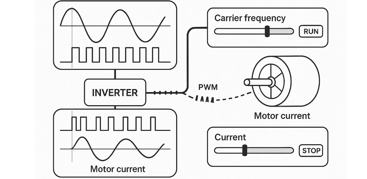
In a simplified PWM drawing, the drive compares a desired low-frequency waveform with a faster carrier to determine pulse widths. The motor’s inductance smooths much of the high-frequency content in its current; the voltage at the drive output still consists of fast pulses. The original illustration below shows this relationship. Its 0.5–16 kHz slider is a teaching range, not a promise that every VFD permits all those settings or behaves exactly like the diagram.
See the carrier and PWM pulses
Adjust the carrier control while observing the pulse pattern and motor illustration. The demonstration simplifies real switching patterns, thermal behavior and sound; the drive manual and motor measurements determine what is suitable on a machine.
How to read the right-hand bars: From top to bottom, they illustrate relative drive heating, electromagnetic effects and audible switching noise. They are not measurements of temperature, decibels, current or EMC compliance. The rotor speed is slowed deliberately so the mechanism remains visible; it does not claim to show the real motor rpm.
What changes when the carrier frequency is higher?
Motor sound: on many motor and drive combinations, raising the carrier shifts or reduces the audible switching whine. A lower carrier can make the motor’s electrical hum more noticeable. Mechanical resonance, motor construction and the drive’s PWM method also matter; changing this setting will not cure every noise. Schneider Electric’s ATV320 guidance describes the quieter-operation versus extra drive heat tradeoff.
The original field note describes an unpleasant tone from some motors at low speed. A PWM-related whine can shift as you change carrier frequency; mechanical resonance at one motor speed is a separate problem. If a machine should avoid a particular shaft-speed band, the skip-frequency function addresses that operating band. Test the actual source of the sound before changing either setting.
Current ripple: for an otherwise comparable operating point, more frequent pulses can make motor current smoother. That can reduce some vibration and motor heating from ripple. The output voltage is still PWM, and actual results depend on the drive, motor and cable. Rockwell Automation’s PowerFlex reference manual discusses smoother current, audible noise, drive switching losses and current derating together.
Drive temperature and current rating: faster switching generally increases losses in the power semiconductors. Some drives then reduce the permitted continuous output current, lower the switching frequency automatically or both. Danfoss explains why the chosen switching pattern and frequency enter its thermal derating calculations. A quieter motor therefore does not automatically mean a more efficient drive.
EMC and long motor leads: PWM edges produce high-frequency components that can couple into nearby wiring. Carrier choice can affect the interference spectrum, but it cannot substitute for the drive maker’s rules on motor cable length, shielding, grounding, cable separation and output filters. Schneider Electric’s cable-installation guidance specifically requires separating power and control wiring, even when the cable is shielded. If your installation needs a drive filter or accessory, confirm its allowed switching range before changing a parameter.
For long motor cables or insulation-sensitive motors, check whether the drive maker specifies an output reactor, dV/dt filter or sine-wave filter. The carrier setting controls switching frequency; it does not by itself define the voltage edge slope or guarantee safe voltage peaks at the motor. Danfoss’s output-filter design guide treats these cable and motor-side issues separately.
How should you choose the carrier frequency?
Begin with the default and permitted values for your exact drive model. Manuals may call the setting PWM frequency, switching frequency or carrier frequency. The available values and default change with the drive’s power rating, cooling and control mode: for example, the Schneider ATV212 F300 setting is specified as 6–16 kHz for that series, while Rockwell lists other factory defaults and rating-dependent limits for its PowerFlex 750 range. A general “every VFD is 0.5–16 kHz” rule would be wrong.
For a motor near a quiet workspace, check whether a supported higher setting actually improves its sound, then verify motor current, drive temperature and continuous-current derating. For a heavily loaded conveyor or a hot cabinet, the available current and cooling can matter more than the last reduction in whine. On a long cable run or a machine with sensitive instruments, first check the installation manual’s cable and EMC filter guidance; a carrier adjustment alone may not solve electrical interference.
Treat the widget’s bars for sound, heat and interference as qualitative teaching cues. They do not predict decibels, semiconductor temperature, motor current or compliance for a real installation. A V/f setting, vector-control setting or a change in base frequency addresses different aspects of motor control.
Carrier frequency: quick answers
Does a higher carrier increase motor speed or torque? No direct speed command is created by this setting. Speed is primarily tied to the commanded output frequency and motor slip; delivered torque is constrained by the motor, load and drive-current limits. The carrier can change current ripple, noise and available drive current, which may affect how the complete system behaves.
Is a higher carrier always quieter? Often it reduces a particular PWM whine, but the audible result depends on the motor, installation and switching strategy. Listen and measure under the relevant load; stay within the model’s thermal and current limits.
Can I use 16 kHz on any VFD? No. The illustration includes 16 kHz only as an example. Some drives or power sizes do not offer it, and others require current derating at high switching frequency. Read the exact model’s manual and any attached filter’s instructions.
Are carrier and switching frequency the same? In many VFD manuals, these names refer to the adjustable PWM frequency. The detailed timing can vary with modulation method and automatic thermal control, so use the definitions and parameter instructions for the specific drive.
Understand the waveform: PWM explained · switching frequency · IGBT power switches · motor base frequency · motor rated frequency.
See the system tradeoffs: V/f control · vector control · how an AC drive works · current limiting · EMC filters · motor slip.
Installation details: output reactors · skip frequency and mechanical resonance · EMC filters.
Keep learning: VFD technical library · AC drives · VFD selection and essential settings.
Manufacturer references: Rockwell Automation PowerFlex manual · Schneider Electric on sound and heat · Danfoss on thermal derating. Product settings vary; consult the manual for the drive you are installing.