
what is High Speed Output ?
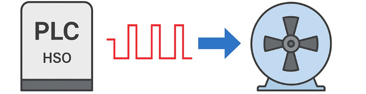
High-Speed Output (HSO) is a feature that allows a PLC or suitable output module to generate fast digital signals. Pulse-train and PWM capabilities depend on the supported CPU and output hardware. The aim is to manage pulse count and timing to suit the application. The HSO label does not establish identical speeds or functions across all PLCs.
How does HSO command a motor? In motion applications, the PLC pulse output connects to the command input of a suitable stepper drive or pulse-input servo drive. The drive supplies power to the motor. A stepper motor or servo motor is not powered directly by the PLC's HSO channel. The pulse connection carries commands and has a different role from the motor power connection.
HSO and high-speed counters: HSO generates pulses; a high-speed counter (HSC) counts incoming pulses. Encoder signals can be evaluated through suitable HSC inputs. Some controllers share hardware resources between these functions. “High-speed counter output” should not be used as the general name for high-speed pulse output.
Which output hardware is required? Fast pulse generation generally uses suitable transistor outputs or dedicated modules. Check PTO/PWM support when selecting an I/O module channel. Mechanical relay outputs are unsuitable for high-frequency pulse trains. An output being digital or transistor-based does not, by itself, establish support for high-speed pulse generation.
PTO — Pulse Train Output: PTO generates command pulses in a format accepted by the drive for position control. Pulse count relates to commanded movement, while pulse frequency relates to commanded speed. The relationship depends on the drive's pulses-per-revolution setting and the mechanics. Transmitted pulse count is not a measurement of actual position.
PWM — Pulse Width Modulation: In PWM, the on-time as a proportion of the full period is the duty cycle. D = tON / T × 100%. Frequency and duty cycle are separate quantities; how they are configured depends on the controller. A device receiving PWM commands needs a compatible input interface and power stage.
Pulse and direction formats: Some systems use pulse + direction; others use separate forward/reverse pulse channels or phase-related A/B signals. Check edge detection and counting behaviour against the receiving device's configuration. PLC and drive formats must match; consult the drive documentation for direction-signal timing requirements.
Electrical compatibility: Verify voltage levels, output type, input current, common connections and wiring format together. Sink/source, open-collector and differential line-driver interfaces require different wiring arrangements. Levels such as 5 V and 24 V vary by model. Matching connectors or pulse frequencies alone does not establish electrical compatibility.
Program and channel configuration: Configure the pulse channel, output mode and axis parameters in the programming software. Appropriate commands may be executed through FBD or Structured Text. Prevent other output commands from conflicting with a reserved pulse channel. Toggling an output in the normal program cycle differs from using the hardware pulse generator.
Calculating motor speed from pulse frequency: n = 60 × f / N, where f is command frequency in Hz, N is the command pulses required for one motor revolution, and n is speed in rpm. Account for the drive's electronic gearing or microstep settings when establishing N. Do not confuse command pulses per revolution with encoder resolution.
Speed example: With the drive configured for 4,000 command pulses per motor revolution, a 20 kHz = 20,000 pulses/s command gives n = 60 × 20,000 / 4,000 = 300 rpm. This is commanded motor speed; whether the motor follows it under load must be assessed separately.
Calculating travel from pulse count: At the same setting, 12,000 pulses command three motor revolutions. If the motor directly turns a screw with 5 mm travel per revolution, without a gearbox, theoretical travel is 3 × 5 = 15 mm. Changing the gearbox ratio, screw lead or command scaling changes the travel calculation.
Resolution is different from accuracy: The example's theoretical command increment is 5 mm / 4,000 = 0.00125 mm = 1.25 µm. This is not the system's actual positioning accuracy. Backlash, compliance, motor behaviour, load and measurement affect the result. Smaller pulse increments or more microsteps do not guarantee a proportional improvement in accuracy.
Frequency and pulse-width limits: A 20 kHz signal has a 50 µs period; at 50% duty cycle, high and low times are 25 µs each. Both the PLC channel and drive input must support these timings. Check maximum frequency, minimum pulse duration and permitted load in the channel specifications; there is no universal value for every HSO.
Acceleration and deceleration: An immediate jump to a high pulse frequency can cause tracking problems depending on the motor and load. Configure speed, acceleration and deceleration limits together. Supported axes may offer profiles such as an S-curve. Selecting an appropriate motion profile involves more than using the output's maximum frequency.
How is actual position checked? Servo feedback and suitable encoder-equipped stepper systems can help compare commanded and actual movement. Determine the reference position, drive diagnostics and any load-side measurement requirements for the application. The PLC completing its pulse train does not, by itself, confirm that the mechanism reached its target.
Synchronisation and delay: For multiple axes, consider start timing, pulse generation, drive response and mechanical tracking together. Choose task scheduling or a suitable EtherCAT / PROFINET motion solution according to the supported architecture. Using high-speed outputs alone does not guarantee zero delay or exact synchronisation between axes.
What should you check while debugging? During debugging, inspect channel assignment, command format, frequency, pulse count, direction and drive alarms. Use appropriate measurements to confirm that pulses reach the receiving input. HMI or SCADA values can help diagnosis. A displayed command or output LED does not establish that the waveform and actual movement have been verified.
Applications and selection: Suitable pulse-input motion systems can serve packaging, indexing, dosing and printing machines. When selecting a PLC, assess axis count, command resolution, required frequency, electrical interface and feedback together. Not every servo drive accepts pulse commands; verify its supported interface before selection.
Machine safety: Design safety functions to suit the risk assessment. Where required, consider STO with a suitable safety relay or safety controller. Stopping pulse commands alone is not a validated safe stop. Include drive stopping behaviour and the mechanical load in the safety design.