
What is a multiple time relay?
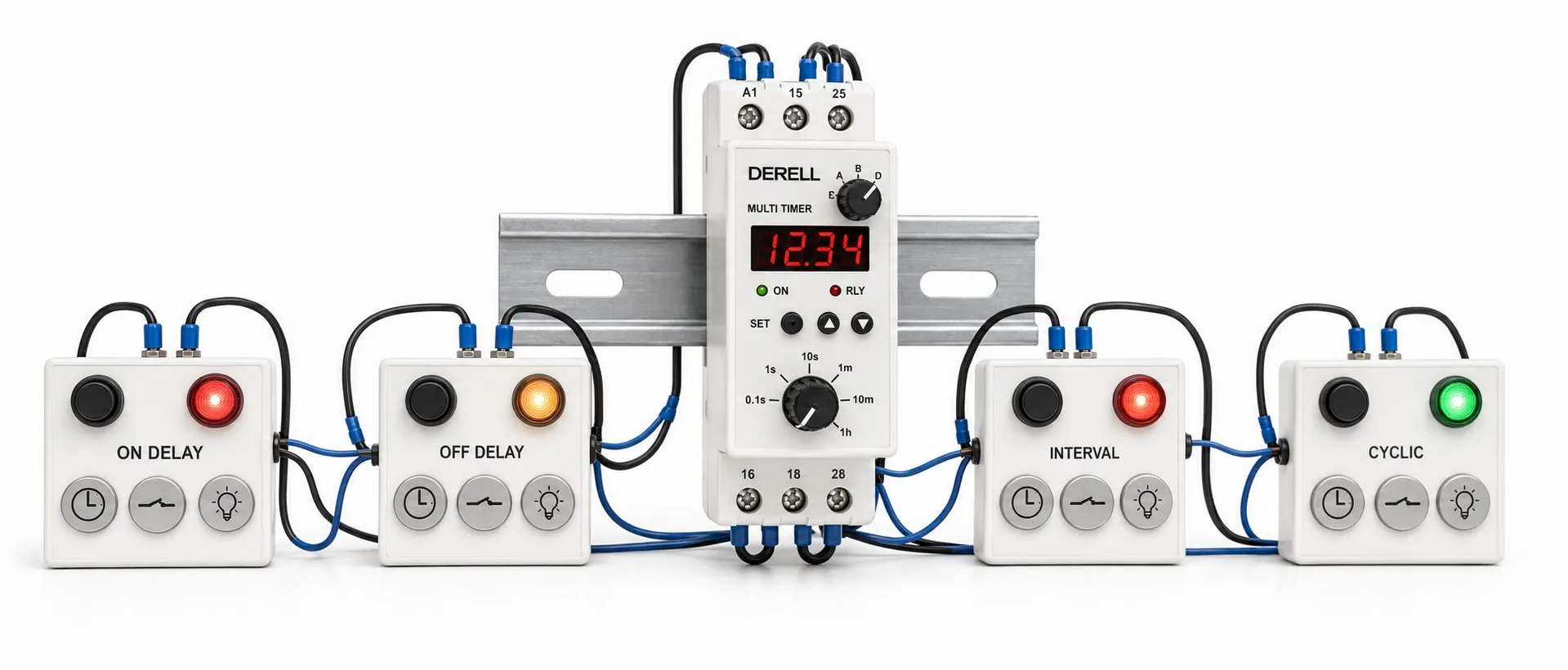
Selectable timing functions in one device
A multifunction timer relay is a control device that offers a choice of timing behaviours. A suitable model might provide delayed starting in one circuit and repeated on/off cycling in another. This flexibility in a timer relay does not mean that several functions run independently at the same time; common models operate in one selected mode.
Editor's note: Multifunction, multi-range and multi-channel describe different capabilities. Multifunction means selecting the operating behaviour; multi-range means selecting the timing scale. A multi-channel device controls independent outputs only where its specifications explicitly provide for this. Two changeover contacts or two time settings do not, by themselves, establish that the device contains two independent timers.
What does the selected mode change?
To understand how the relay works, examine the relationship between the supply, trigger signal, elapsed time and output. Selecting a function changes this relationship. Mode letters such as A, B or C do not have universal meanings across manufacturers; use the timing diagram for the specific model.
ON-delay: In on-delay operation, timing begins when the starting condition occurs, and the output activates after the delay. OFF-delay: In off-delay operation, the output remains active for a defined period after the control signal disappears. Many signal-triggered OFF-delay models need a continuous supply throughout this period.
Timed output: With a suitable interval or one-shot function, the starting condition activates the output, which switches off after the selected duration. Repeated cycling: A flasher function repeats on and off periods. Whether the cycle starts on or off, and whether the two periods are equal or independently adjustable, depends on the model.
Special tasks such as star-delta changeover require an appropriate output sequence and transition interval. This function is available only on suitable models. Checking the required timing diagram is more useful than choosing by the number of available functions.
Time range and time setting are different
The time range defines the available scale; the time setting selects a value within it. For example, a 0–10-second range can provide a five-second delay. Changing to a minutes range gives a different duration at the same dial position. During adjustment, read the function, time unit, range and setting together. Options may extend from milliseconds to hours; the available span varies by model.
Analog-adjusted models generally use dials and selectors, while digital models use buttons and a display. Numerical indication, setting resolution, setting error and repeatability are separate properties. In cycling mode, T1 and T2 settings often describe the on and off periods of one cycle; they do not establish two independent control channels.
Supply and triggering serve different purposes
Some models begin timing when power is applied; others remain powered and wait for a separate input. When designing a timing circuit, distinguish a voltage input from a volt-free contact input. Do not apply an external voltage to a contact input unless the wiring instructions specify it. Verify any wide supply range against the full model code: “multifunction” does not mean compatibility with every AC/DC voltage.
Retriggering and reset behaviour directly affect the application. A second signal before timeout may restart timing or be ignored. Check separately whether elapsed time is retained after a power interruption. If a momentary pushbutton pulse must initiate a complete cycle, the selected mode must support that behaviour.
Two contacts do not mean two independent timers
In the output arrangement, two changeover contacts may operate together from the same timing decision. Other models provide one instantaneous contact and one timed contact. Independently timed outputs must be explicitly specified when required. NO and NC identify the contacts' normal states; the selected mode's timing diagram shows their switching sequence.
Volt-free relay contacts switch an external circuit; they do not generate a voltage. With semiconductor-output models, check the output type and load compatibility separately. For a motor, valve or lamp, the headline current rating is insufficient on its own. Load type, inrush current and switching frequency may require an interposing relay or contactor.
Where is it useful in practice?
In control circuits, OFF-delay can keep a fan running for 30 seconds after a stop command, while a cycling function can flash an indicator lamp. These are separate application examples; do not assume one output controls both independently. Running a pump for a set time also does not measure liquid level or delivered volume; provide suitable sensing where the process depends on that information.
Delaying a motor start does not provide soft starting. A timer relay does not ramp motor voltage, current or speed. Consider a real-time-clock timer for daily scheduled operation, or an astronomical time switch for lighting that follows sunrise and sunset. Measuring elapsed time and following a calendar address different needs.
A general-purpose multifunction timer relay must not be used to delay an emergency stop or replace a safety relay. Any safety-related delay requires equipment suitable for the defined safety function and a validated circuit design.
Selection, commissioning and checks
During model selection, establish the required timing diagram first, then the supply and input compatibility, time range, output arrangement, load capacity and mounting method. Make adjustments according to the manufacturer's instructions, with power removed where required. Initial checks should cover starting, early signal removal, retriggering and power restoration. Compare measured timing with the application's permitted tolerance.
Several conditions and process steps may call for a programmable timer relay or a suitable controller. If one function will always be used, a simple timer relay may keep adjustment more straightforward. A multifunction product can reduce the variety of spare devices needed for different tasks; it does not automatically replace every independent relay required simultaneously.
During fault diagnosis, check the mode, time unit, input signal and supply first. A very short trigger pulse may not be detected, and insufficient reset time can disrupt the next cycle. An illuminated output LED does not prove that the load circuit is healthy. Inspect the contacts, socket and load connections as well.
Related products and topics
Timer relays, analog timer relays, timer relay prices and timer relay types.