
Frequency Sensitive Fuses
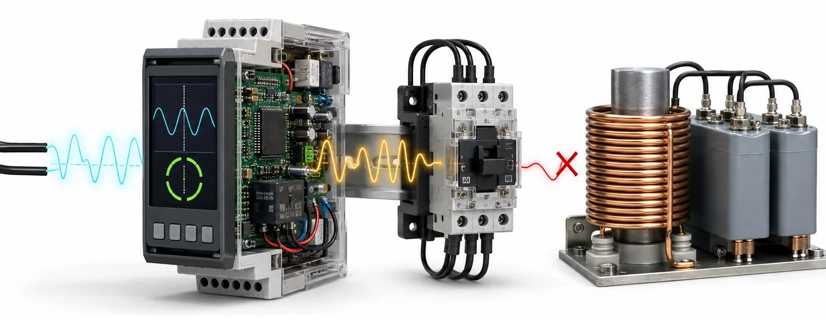
Separating overcurrent protection from frequency monitoring
Hello everyone. When you encounter the term frequency-sensitive fuse, first establish which protection function is meant. A conventional fusible-link fuse operates through heating caused by the current flowing through it; it does not behave like a relay that measures a preset frequency. Current frequency can affect a fuse's operating conditions, but being affected by frequency and measuring frequency to initiate a trip are different functions.
Editor's note: Describing a fuse as a device that “opens above 1200 Hz” requires explicit technical documentation for that particular product. Such a threshold cannot be assigned to an ordinary fusible-link fuse. Likewise, a fast-acting fuse is not a high-frequency detector. Monitoring a frequency limit requires suitable equipment with measurement and tripping functions.
What actually happens inside a fuse?
The basic purpose of an electrical fuse is to interrupt overcurrent under its specified conditions. When heat generated in the metal element sufficiently exceeds the heat dissipated to its surroundings, the element melts; the resulting electrical arc must then be extinguished safely. Selection therefore involves the time-current curve, voltage rating, breaking capacity and installation conditions, as well as the ampere rating.
For a single-frequency current, losses can be approximated by P = IRMS2 × RAC(f). Effective resistance can change with frequency. At high frequencies, skin effect can concentrate current toward a conductor's surface, while proximity effect can redistribute current because of fields from nearby conductors. In some fuses, the result can be greater local heating and a need to reduce the permissible continuous current. There is no single correction percentage that applies to every fuse.
Why harmonics matter
A current waveform that departs from a sine wave may contain harmonic components alongside its fundamental. For example, a waveform containing a 10 A RMS component at 50 Hz and a 4 A RMS component at 250 Hz, with no other components, has a total of approximately 10.77 A RMS: IRMS = √(102 + 42). Assuming unchanged resistance, this produces about 16% more resistive heat than the 10 A fundamental alone. This calculation does not predict fuse opening time; it explains why considering only the fundamental is incomplete.
Actual selection considers total RMS current, frequency content and enclosure temperature together. Determining the fuse current rating from the equipment's power rating alone is insufficient. Where the manufacturer provides corrections for frequency, temperature and connections, apply them using that manufacturer's method.
Do not confuse the three frequencies in a drive
In a variable frequency drive, the supply may operate at 50 Hz while the motor output fundamental is, for example, 35 Hz and the inverter's PWM switching frequency is 8 kHz. These are different quantities. An 8 kHz carrier frequency does not mean the input fuse carries a sinusoidal current at that frequency or should open at 8 kHz. Whether the fuse is installed on the input, in the DC link or in another circuit branch changes the assessment.
Input protection should follow the drive manufacturer's specified fuse types and coordination requirements. I2t coordination can be important for semiconductor protection fuses, but an arbitrary fast fuse cannot be assumed to protect every power semiconductor. Choosing between fast-acting and time-delay fuses is also not a matter of setting a frequency threshold. For DC-link applications, check DC fuse suitability and the circuit's interruption conditions.
How actual frequency protection works
If the aim is to disconnect a load when generator or supply frequency moves outside its limits, use an underfrequency/overfrequency protection relay or a controller with that function. The device determines frequency from a suitable measurement input and issues a trip command when the configured limits and timing conditions are met. A suitable contactor or circuit breaker disconnects the power circuit. The measuring device and the power switching device may be separate components; the fuse continues to provide overcurrent protection.
High-frequency interference may require a different solution. An EMC filter helps attenuate conducted electromagnetic noise in particular frequency bands; a harmonic filter targets particular harmonic components according to its design. Their functions also differ from those of a frequency relay. Start by identifying overcurrent, frequency deviation and electromagnetic interference as separate problems.
Selection and fault investigation
Fuse selection requires the normal operating current, inrush pulses, duty cycle, ambient temperature, AC/DC voltage and prospective short-circuit current. Read the relevant fuse standards alongside the manufacturer's data sheet. Matching amperes and physical dimensions does not establish equivalence. With power supplies, consider initial energisation current; in UPS systems, identify which power path the fuse protects.
If a fuse repeatedly opens, investigate why the fuse is blowing before fitting a higher ampere rating. Examine true RMS current, measurement bandwidth where relevant, operating events and fuseholder maintenance together. Loose or oxidised contacts can also generate heat. When assessing replacement requirements, remember that a fusible-link fuse cannot be reused after opening. Apply the appropriate replacement safety precautions, including energy isolation and any specified DC-link discharge time.
Related topics
Within the fuse family, compare current fuses, industrial fuses, semiconductor protection fuses, DC fuses and fast-acting and time-delay types. For the wider application, explore variable frequency drives, EMC filters, harmonic filters, power supplies and uninterruptible power supplies.
Continue with which fuse type to choose, compare the differences between fuse types, or browse the fuses product category.