
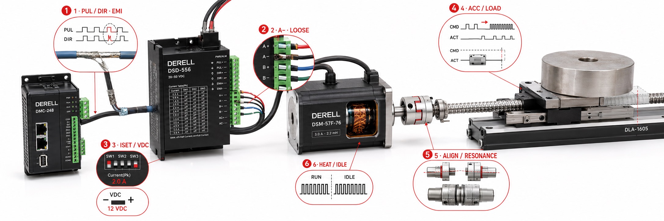
Common stepper motor problems: symptoms, causes and troubleshooting
Hello everyone. If a stepper motor system refuses to turn, vibrates or misses its target position, the motor itself is only one possible cause. Check the motion command, driver settings, power supply, wiring and mechanical load together. Our guides to stepper motor operation and driver operation explain this chain. Similar symptoms can have different causes in applications ranging from CNC axes to 3D printers.
Effective troubleshooting starts by identifying the conditions that trigger the fault. Does it happen during acceleration, after a direction change, once the system warms up, or when another device switches on? These patterns provide better clues than changing settings at random.
1. The motor will not turn, or only hums
Start with the driver alarm, power-supply status and enable-input logic. An active enable input energizes some drivers and disables others; follow the specific manual. A powered driver is not necessarily receiving a valid motion command. Check the levels, pulse width and wiring of the STEP and DIR signals. With a PLC, verify that a suitable high-speed output and pulse-generation function are being used.
Incorrect phase pairing, a disconnected motor lead or an unreleased mechanical brake can cause humming, vibration and low torque. Do not assume that wire colours are universal. Use the wiring diagram for the correct motor type. Before investigating a mechanical jam, isolate power, support any load that could fall and verify that the system is de-energized. Do not connect or disconnect motor leads while the driver is powered.
2. Missed steps and sudden stalling
Missed steps occur when the rotor cannot follow the commanded movement. Excessive load, aggressive acceleration, an excessive starting speed, insufficient phase current or a supply-voltage dip can trigger them. A motor's stationary holding torque is not its available torque at high speed. Assess stepper motor torque behaviour at the intended operating speed.
During a safe test, reduce starting speed and acceleration, then repeat the move at a lower running speed. An improvement makes the motion profile and load demand worth investigating first; it does not prove that the motor is fault-free. Our guides to speed and position control and supply-voltage selection help with this assessment. Do not treat higher current as the answer to every missed step; stay within the motor and driver ratings.
3. Position error: missed steps or incorrect scaling?
If travel is wrong by roughly the same proportion over different distances, check pulses per millimetre, the microstep setting, screw lead and gear ratio. This differs from missed steps under load. A directly coupled 1.8° motor, configured for an external command resolution of 1/8 microstepping and a screw lead of 5 mm per revolution, needs a nominal (200 × 8) / 5 = 320 pulses/mm. This example has no gearbox; changes to command resolution or the gear mechanism change the calculation.
If the error appears mainly after reversing direction, investigate backlash, a loose coupling or a slipping belt pulley. If homing gives a different result each time, inspect the limit/home switch, sensor mounting and homing sequence. On a system without position feedback, the controller's displayed position may be a count of commanded movement rather than a measurement of actual position.
4. Vibration and resonance at particular speeds
If vibration becomes severe within a narrow speed range, consider resonance. The motor, attached inertia, mechanical compliance and mounting all influence it; there is no universal resonance speed for every stepper system. Microstepping and other drive modes can reduce vibration, but cannot remove misalignment or inadequate torque.
Observe the effects of controlled changes to speed range, acceleration profile and mounting rigidity. Loose mounting and worn bearings can produce similar noises. Some operating noise may be normal, but a new or progressively louder noise deserves investigation. Understanding stepper motor advantages and limitations helps establish realistic expectations.
5. The motor or driver overheats
A stepper motor can draw current at standstill, so heating while stationary is possible. Whether this is abnormal depends on measured temperature, manufacturer limits, ambient conditions and operating duration. Touch is not a temperature measurement. Check phase-current settings, cooling and standstill current first. Our guide to stepper motor thermal management explains these factors.
Compare the peak/RMS current conventions in the motor and driver documentation. A higher microstep count does not automatically mean more heating; effective phase currents and operating conditions matter. On suitable drivers, reducing standstill current may help, but also reduces holding torque. The driver's PWM current regulation does not remove its cooling requirements. Resolve the cause of repeated thermal alarms instead of repeatedly resetting them.
6. Random movement and electrical interference
If the fault occurs when a contactor, brake coil or another drive switches, investigate electrical interference and supply transients. Route command cables appropriately away from power and motor cables; apply twisted pairs, shielding and grounding as specified in the equipment manuals. Check the signal common, input voltage and NPN/PNP interface principles as well.
An oscilloscope, used with suitable probes and measurement methods, helps examine pulse shape and timing at the driver input. A multimeter may display an average value, but cannot reliably reveal brief interference or missing pulses. Shield termination and input filtering require a system-specific approach. Excessive filtering can also prevent valid pulses from being detected.
7. Supply, connection and driver faults
Voltage dips under load, loose terminals, long or undersized supply cables and power-supply current limiting can disrupt motion. An unloaded voltage reading is not enough. Evaluate the voltage at the driver input under the conditions that produce the fault. Do not equate power-supply current directly with motor phase current.
Record the alarm code and when it appears. Overcurrent, undervoltage and temperature alarms are model-specific; do not interpret one brand's code using another brand's table. On a de-energized motor disconnected from the driver, winding resistance can be compared according to its wiring diagram; a resistance check does not rule out every winding or insulation fault. Complete wiring and mechanical checks before condemning the driver. Our maintenance and repair guide supports this stage.
8. What does feedback change?
An open-loop system does not automatically verify that the shaft reached its target. A suitable closed-loop stepper system evaluates encoder feedback. A motor-mounted encoder does not necessarily measure coupling slip or screw backlash downstream. Measuring load position with a linear encoder is a different feedback arrangement.
Feedback does not give a motor unlimited torque. If the application needs sustained high speed, heavy loads or high dynamic performance, reconsider the system using our stepper versus servo comparison. Motor and driver selection should account for more than frame size or holding torque.
A practical troubleshooting sequence
Record the symptom first: note the model, alarm, load, speed, acceleration, current setting and operating duration. Then examine power and wiring, command signals, the motion profile and mechanical condition in order. Change one variable per test, and compare the result with the original settings.
After correcting the fault, re-home the axis as appropriate and verify repeated movements under the real load. A motor turning once does not establish that the positioning problem has been solved. Monitor temperature, position repeatability and alarms throughout a complete operating cycle.