
How do stepper motor drivers work?
Hello everyone. A stepper motor driver converts motion commands from a controller into the phase currents applied to the motor windings. The controller specifies the movement, the power supply provides energy, and the driver manages that energy. Reading about how a stepper motor works makes the driver's role clearer: control current magnitude, direction and sequence to establish a new target position for the rotor.
Animation: full steps and microsteps
The two ideal examples below illustrate two-phase bipolar operation. The solid orange line represents phase A; the dashed blue line represents phase B. The rotor symbol and current markers advance together. Use Pause to inspect a state or One step to advance to the next target.
Full step — 4 commands / electrical cycle
1/4 microstep — 16 commands / electrical cycle
This is a slowed, enlarged electrical-cycle illustration, not actual shaft motion or measured current. The full-step example energizes both phases and uses currents normalized for constant resultant magnitude. The same cycle takes 4 commands on the left and 16 on the right. For a motor with a 1.8° full-step angle, quarter stepping gives a nominal command increment of 0.45°; the large angles in the drawing are not shaft angles. See stepper motor resolution and drive modes for more detail.
1. What do STEP and DIR commands do?
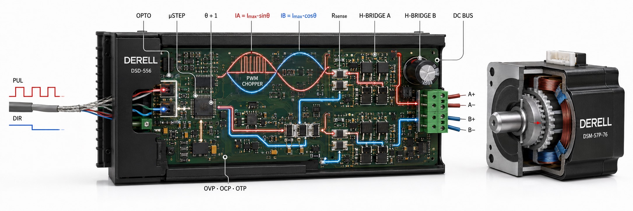
A STEP pulse requests the next target in the driver's current table. The DIR signal selects the direction through that sequence. Pulse count specifies nominal travel, while pulse frequency specifies nominal speed; the controller also plans acceleration. Our pages on required control signals and speed and position control explain these relationships.
When using a PLC, choose a suitable high-speed pulse output. Check the driver's manual for input voltage, minimum pulse width, direction timing and common-terminal wiring. Understanding NPN/PNP wiring principles can help with the interface, but a sensor output or ordinary PLC output is not automatically suitable for a STEP input.
2. H-bridges control phase-current direction
Common bipolar drivers supply phases A and B through separate H-bridges. Their switches control the voltage across each winding and the direction of phase current. A motor can contain many physical coils; two electrical phases do not necessarily mean just two physical coils. A unipolar connection uses sections of centre-tapped windings. Check the motor wiring diagram alongside our guide to stepper motor types.
3. How do PWM and chopping limit current?
A current-regulated chopper driver monitors phase current and rapidly switches its power stage to follow the current target. PWM here concerns power-stage switching. STEP frequency and PWM switching frequency serve different purposes. Winding inductance means that current does not disappear instantly when a switch turns off; it continues through the driver's recirculation paths.
The motor's rated winding voltage need not equal the supply voltage of a current-regulated driver. Supply voltage affects how quickly current reaches its target, particularly at higher speeds, but the driver's limits must be respected. Consider supply-voltage selection together with speed and torque behaviour. Also, phase current and current drawn from the power supply are different measurements.
4. Microstepping creates smaller targets
In microstepping mode, the ratio between A and B currents changes in smaller increments; ideal targets follow sine and cosine relationships. This provides smaller command increments and smoother movement. Higher resolution does not guarantee an equally large improvement in positioning accuracy. Load, friction, motor construction and current-regulation quality affect the result. Our guides to stepper motor advantages and limitations and gear mechanisms also explain relevant mechanical factors.
5. Decay describes how current decreases
Slow decay, fast decay and mixed decay describe the electrical paths used as phase current falls toward its target. “Decay” does not mean that the driver is faulty or deteriorating. The appropriate setting depends on the motor, supply, speed and current level. No single mode gives the best result under every operating condition.
6. Current regulation does not measure shaft position
Regulating phase current alone does not confirm that the shaft reached its target. In an open-loop system, excessive load or abrupt acceleration can cause missed steps. Suitable closed-loop systems also evaluate position feedback from an encoder. Our articles on stepper versus servo motors and common stepper motor problems help set realistic expectations.
Some drivers provide overcurrent protection, undervoltage lockout or thermal protection; availability and coverage depend on the model. Reducing standstill current can lower heating, but also reduces holding torque. Pay attention to thermal management and maintenance checks. Holding torque must not be treated as a safety brake for a vertical load.
Which specifications should you compare?
Check phase wiring, motor rated current, the driver's peak/RMS current convention, supply range, signal compatibility and cooling requirements together. Do not assume universal wire colours or change motor connections while the driver is powered. Our motor and driver buying guide takes a system-wide approach. When comparing motor and driver prices, consider operating speed and load as well as the advertised microstep count.