
What signals are required for the control of stepper motors?
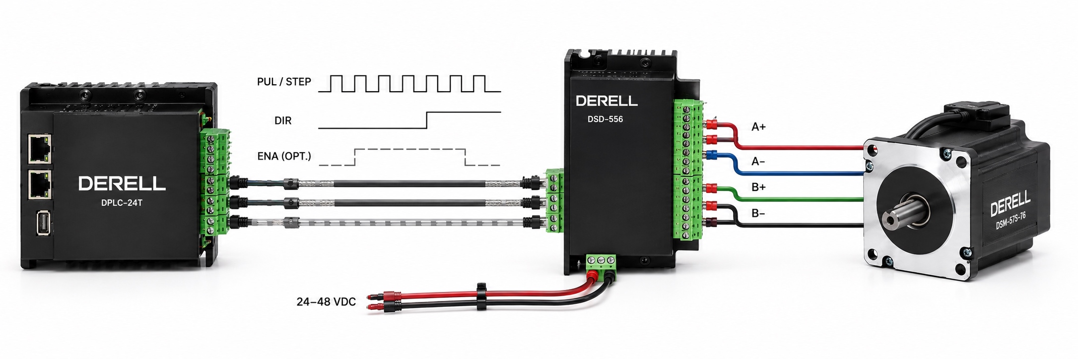
Which signals are needed to control a stepper motor?
Hello everyone. In common pulse-controlled systems, STEP/PUL commands movement increments, DIR selects direction, and ENA/ENABLE controls whether the driver is enabled. These control signals go to the driver inputs, not the motor windings. The stepper driver regulates phase currents; the motor's operating principle relies on the magnetic action produced by those currents.
Stepper systems do not all use the same interface. Some accept separate pulses for each direction; others receive motion commands over a communication network. This page covers the STEP/DIR interface. The stepper motor knowledge hub explains the wider system.
STEP/PUL: How far and how fast?
A STEP pulse produces a command increment at the active edge accepted by the driver. Check the manual for that edge and the minimum pulse durations. Pulse count determines commanded travel; pulse frequency determines commanded speed. Speed and position control also requires suitable acceleration and deceleration ramps.
A 1.8° motor needs 200 pulses/rev in full-step mode. At 1/16 microstepping, it needs 3200 pulses/rev. Without electronic gearing, speed (rpm) = 60 × pulse frequency / pulses per revolution. A resolution calculation gives the command increment; sending a pulse does not prove that the shaft moved.
DIR: How is direction changed?
The DIR signal selects which direction pulses command. There is no universal rule that a high level means clockwise: wiring, driver settings and viewing direction affect the result. Setup time and hold time specify how long DIR must remain stable before and after the active STEP edge. Decelerate a loaded system appropriately before reversing it.
ENA/ENABLE: Is disabling the driver the same as stopping pulses?
No. Stopping pulses stops motion commands; an enabled driver may continue holding the motor in position. Disabling the driver switches off its power outputs according to the model's behaviour. Check the manual for ENA polarity, its default state when unconnected, and the delay before operation resumes. Consider holding torque together with standby current and heating.
Animation: STEP, DIR and microstepping
Start the animation, then pause to change direction or microstepping. Select Driver disabled to see incoming pulses without any advance in the commanded shaft position.
STEP 0 DIR 0
Input pulses: 0
Accepted pulses: 0
Commanded angle: 0.0000°
Driver enabled
Example motor: 1.8°; 200 accepted full-step pulses or 3200 at 1/16 command one revolution. The pointer shows ideal command position; load, lost steps and free shaft movement are not modelled. The DIR 0/1 mapping belongs to this example. Pulses are slowed for visibility. Resetting the demo is not machine homing.
Microstep selection, RESET and fault signals
Microstep selection may use MODE inputs, DIP switches or software; extra control pins are not required on every driver. Changing the full-step, half-step or microstep setting changes the angle commanded by a given pulse count. RESET may reset internal logic or a fault state; resetting the driver does not automatically establish the machine's mechanical reference.
ALARM/FAULT is usually an output from the driver to the controller. It may use an open collector, a relay or another output circuit. READY may indicate readiness. During fault diagnosis, check both signal polarity and the fault code; correct the cause before clearing the alarm.
Voltage compatibility and wiring arrangements
A 5 V logic input is not automatically compatible with a 24 V PLC output. With optically isolated inputs, input current matters as well as voltage. PUL+/PUL− and DIR+/DIR− identify input pairs; a driver may accept differential, NPN/open-collector or PNP connections under specified conditions. Common-anode and common-cathode arrangements are different. Use the model's wiring diagram rather than a universal connection scheme.
Driver supply voltage and control-input voltage are different. Choosing a suitable motor power supply does not mean the same voltage can be applied to STEP. Follow the manufacturer's input circuit and connection instructions rather than choosing an arbitrary series resistor.
How are interference and actual movement checked?
Check pulse width, low-level duration, maximum input frequency and the signal return path. Routing signal cables separately from motor and power cables, with suitable twisted pairs and shielding, reduces the risk of false pulses. Mechanical inspection should also cover slipping couplings and binding. With a gear ratio, motor angle and output angle are different.
In an open-loop system, the controller counts its commands. An encoder-equipped stepper and a suitable driver can compare actual position with the command; feedback does not eliminate every mechanical error. Consider the application, stepper limitations and differences from servo systems together.
Technical references: Texas Instruments — DRV8825 inputs and timing; Leadshine — DM542E control connections. Use your own device's manual for applicable values.