
What are the gear mechanisms used in stepper motors?
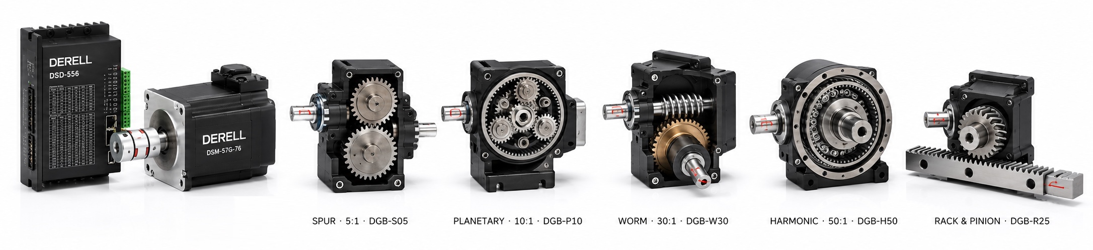
What gear mechanisms are used with stepper motors?
Hello everyone. The load driven by a stepper motor does not always connect directly to its shaft. A gear mechanism or gearbox changes the motion's speed, torque, direction and output step interval. In stepper motor applications such as rotary tables, dosing mechanisms and robot joints, this transmission helps match the motor to the load.
A higher reduction ratio does not always mean a better system. A slower output requires the motor to turn faster, while friction, backlash and flexibility affect the result. The advantages and limitations of stepper motors still apply when gearing is added. The motor's nameplate torque alone is not enough to select a transmission.
Main gear types and their differences
Spur gears: A straightforward transmission
Spur gear teeth run parallel to the shaft axis; a typical pair transfers motion between parallel shafts. Their relatively simple construction can provide an economical solution. However, spur gearing does not automatically provide high accuracy. Gear quality, bearing support, centre distance and backlash matter. When choosing a gearbox, compare output backlash and permissible loads as well as the ratio.
Planetary gears: Compact, coaxial transmission
A planetary gearbox combines a sun gear, planet gears, a planet carrier and an internal ring gear. In a common arrangement, the ring is fixed, the sun is the input and the carrier is the output. Sharing the load across several gears helps transmit high torque in a compact housing. This arrangement can suit robotics and rotary tables, but planetary gearboxes do not all have the same backlash or stiffness.
Helical gears: Smooth engagement with axial thrust
Helical gear teeth sit at an angle to the axis. Gradual engagement can provide smoother, quieter operation in a suitable design. A single helical, parallel shaft transmission also produces axial thrust. This makes bearing selection and shaft support important. Noise requirements must be considered alongside backlash and positioning requirements.
Worm gears: High ratios and an angled drive
A worm and worm wheel transfer motion between shafts that do not intersect and are commonly arranged at right angles. High reduction ratios are possible; sliding contact makes efficiency, lubrication and heat management particularly important. Some designs resist being driven backwards by the load. However, not every worm drive is self-locking; this depends on geometry, friction and operating conditions. A required brake or safe holding arrangement for a vertical load must not be removed simply because worm gearing is used.
Strain wave gears: Precision through a flexible gear element
Strain wave gearing, often called harmonic gearing, uses a wave generator, a thin, flexible externally toothed flexspline and a rigid internally toothed circular spline. Its operating principle depends on controlled deformation of a gear element, rather than a flexible rotating shaft. High ratios and very low backlash are possible in a compact assembly. Low backlash does not mean zero flexibility; torsional deflection and lost motion under load must also be checked. Precision robot joints require consideration of sensors and actuators together.
Bevel gears: Changing the shaft direction
Bevel gears transfer motion between intersecting shaft axes. A 90° arrangement is common, but other angles are possible. The purpose may be to redirect motion rather than reduce speed. A 1:1 bevel gear pair can change direction without providing reduction. In angled and multi-axis mechanisms, speed, torque and position control must be considered alongside the mechanical layout.
How does the gear ratio change speed and torque?
The reduction ratio i = motor speed / output speed. For example, i = 5 means five motor revolutions for one output revolution. In load and transmission calculations, approximate output torque is calculated using the motor's available torque at its operating speed, the ratio and transmission efficiency.
Worked example: A 5:1 gearbox
Motor
500 rpm
0.8 Nm available torque at this speed
Gearbox
i = 5
Assumed efficiency: 90%
Output
500 / 5 = 100 rpm
0.8 × 5 × 0.90 = 3.6 Nm
These values illustrate the calculation; they are not specifications for a particular product. The result is usable only within the gearbox's permissible torque and other mechanical limits. Gears do not create power: losses make output power lower than input power.
Holding torque is specified for a stationary motor and must not automatically be used in this calculation. Use the torque available at the actual motor speed from the motor–driver curve. A 5:1 drive delivering 100 rpm at the output needs 500 rpm at the motor, which also affects speed and position settings.
Resolution improves; accuracy needs separate verification
A motor with a 1.8° step angle has 200 full steps per revolution. With 5:1 reduction, its ideal output full step interval becomes 1.8° / 5 = 0.36°. With 1/16 microstepping, one motor revolution requires 3,200 command pulses and one output revolution requires 16,000 command pulses. The ideal output command interval is 0.0225°. This is the numerical scale described by the resolution calculation.
Command resolution is not actual positioning accuracy. Gear errors, backlash, deflection under load and the motor's microstep behaviour affect the result. When calculating pulse scaling, include the mechanical ratio, driver subdivision and any electronic gearing. Do not apply the same ratio twice.
Why does backlash matter when direction changes?
Backlash allows part of the input motion after a reversal to occur before the output responds. For a hypothetical output backlash of 10 arcminutes, the angle is approximately 0.167°. At the end of a 100 mm arm attached to the output, this angle alone corresponds to approximately 0.29 mm of displacement. This geometric example shows why a small angular value can create a meaningful difference at the end of a mechanism.
Missing a target after reversing direction does not always mean the motor has lost steps. When investigating common stepper system problems, check gear backlash, slipping connections and flexibility separately. Software backlash compensation can help in some arrangements, but it does not repair mechanical wear or remove every deviation under changing loads.
Inertia and acceleration also influence selection
The load inertia reflected to the motor decreases with the square of the ratio in an ideal reduction: Jreflected = Jload / i². A 5:1 ratio reduces this output load contribution to 1/25 at the motor. The inertia of the motor, gearbox and other components must still be included. For the same output movement, the motor turns faster, so acceleration time, speed limits and available torque must be calculated together.
Where does the encoder measure: At the motor or the load?
An encoder measures movement where it is installed. Incremental encoders and absolute encoders provide position information in different ways. Feedback fitted at the motor does not directly measure backlash or coupling slip downstream of the gearbox. Using a stepper motor with an encoder does not automatically eliminate every positioning error at the end of the mechanism.
If actual output position is critical, choose the measurement location accordingly. On a linear axis, a linear encoder or a suitable linear scale can be considered for measuring the moving element's position rather than calculating it from motor revolutions. The benefit of feedback depends on sensor placement and how the control system uses the information.
Couplings, bearing support and mounting loads
Check shaft diameter, flange dimensions, misalignment, radial load and axial load. When selecting metal couplings, consider torque capacity, speed limits and permitted misalignment together. Encoder couplings serve a measuring shaft connection; a coupling designed for an encoder must not be used as a load transmission coupling simply because its dimensions fit.
A long arm or large pulley may exceed the load rating of the motor or gearbox output bearing. Suitable separate bearing support is then required. Forcing parts into alignment can spoil quiet, accurate operation. Check permissible loads at the load distance specified by the manufacturer. Do not confuse continuous torque with a short-duration peak torque rating.
PLC commands, pulses, drivers and reference sensors
When a PLC issues motion commands, the mechanical ratio must be reflected in the program's motion scaling. STEP/DIR signals and pulse frequency must suit the required output speed and total pulses per revolution. The stepper driver regulates motor currents; physical gearbox gearing and the driver's electronic gear setting perform different functions.
A suitable device such as an inductive sensor can detect a metal reference target. The homing approach direction and detection conditions affect repeatability. A reference sensor helps establish a starting point; it must not be assumed to measure position continuously throughout every movement.
Heat, maintenance and total cost
Select the power supply and supply voltage for the motor–driver requirements while separately respecting the gearbox's mechanical limits. Duty cycle, lubrication conditions and ambient temperature matter. A maintenance and repair plan should monitor loose connections, unusual noise, leaks and increasing backlash. Do not add lubricant at random to a sealed, lubricated-for-life gearbox unless the manufacturer requires it.
Selection should consider motor and driver compatibility, stepper system cost and the cost of gearbox options together. If high speed or changing loads are important, include a stepper–servo comparison and servo motor selection in the assessment. The lowest component price may not provide the lowest total cost once commissioning and downtime are included.
Technical references: Oriental Motor: Gearhead selection · Oriental Motor: Stepper motor gearheads · KHK: The ABCs of Gears · KHK: Worm gears · Harmonic Drive: Strain wave gearing
This article provides general technical information. Use the manufacturer's current documentation for product-specific torque, speed, load and maintenance limits. It may be shared with attribution to Otomasyon AVM.
