
Safety features are included in DC drives?
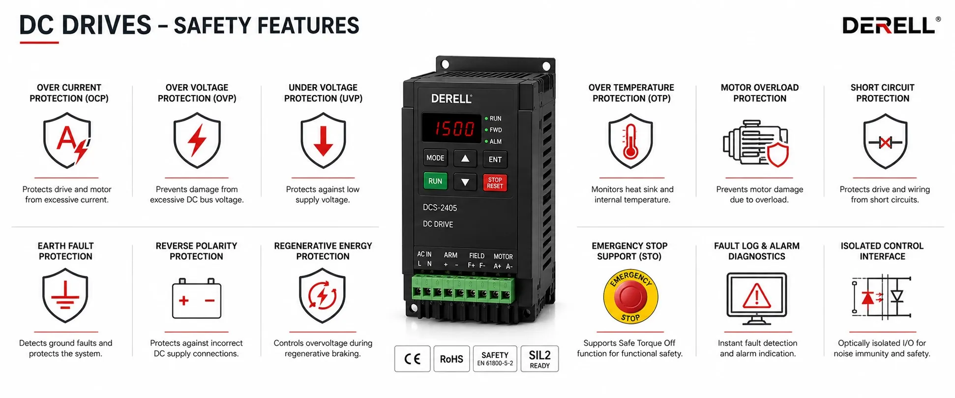
What safety features are available in DC drives?
A DC drive may monitor current, temperature, supply conditions and motor feedback. Some models also support certified safety functions. These capabilities serve different purposes: protecting a converter from damage is not the same as preventing hazardous machine movement.
The distinction applies equally to DC drives, AC variable frequency drives and servo systems. The required safety behavior must be established for the machine, then implemented using equipment that supports it.
Separate protection, normal control and functional safety
Equipment protection addresses conditions such as overload or overheating. Normal control includes speed commands, ramps and positioning. Functional safety concerns the ability of a safety-related control system to perform a defined safety function with the required reliability.
A standard overspeed alarm does not automatically provide safely limited speed. A drive’s fault relay is not automatically a safety relay. Likewise, a software travel limit is not necessarily a safety-rated position limit.
Risk assessment determines what the machine needs. Approaches such as ISO 13849 address the safety-related control system as a whole, including the input devices, logic and final control elements.
What STO actually provides
Safe Torque Off, or STO, prevents the application of torque-producing energy through a supported safety function. It is available on some DC drive designs, but it must not be assumed present on every model. The safety manual defines the required wiring, external equipment and permitted use.
STO is not electrical isolation, a mechanical brake or a guarantee of stopping within a particular time. A rotating load may continue moving through inertia. Gravity or another external force may also move the mechanism after motor torque has been removed.
Hazardous voltage can remain in motor connections or auxiliary circuits. An active STO indication is therefore not proof that equipment is safe to touch. These limitations also matter when using STO-equipped AC drives and servo motor systems.
Emergency stopping may require a controlled sequence
An emergency-stop function is a machine-level measure intended to reduce risk. A pushbutton connected to an ordinary drive input, or an “emergency stop” message on the display, does not by itself establish a compliant safety function.
Some applications permit immediate torque removal. Others require controlled deceleration before torque is removed. Where supported, Safe Stop 1, or SS1, provides a sequence that leads from controlled deceleration to STO. The timing and monitoring arrangement depend on the implemented function.
A normal speed-control ramp is not automatically safety-rated. The input device, safety logic, converter and any required brake must be considered together.
Resetting an emergency stop must not, by itself, restart the machine. Reset, permission to run and the start command need clearly defined behavior. Power restoration and fault recovery should also be assessed for unexpected movement.
Braking and load holding are separate duties
A suspended load can move when motor torque disappears. Such an application may require a suitable mechanical brake or another load-holding arrangement, together with the necessary control and monitoring.
Safe Brake Control does not, by itself, prove that the mechanical brake can hold the load. Brake sizing, condition and the required checking procedures remain important.
A braking resistor dissipates motion energy as heat; it does not replace a holding brake during loss of power. Similarly, normal servo positioning can hold an axis electrically while enabled, but that does not establish load holding after power is removed.
Where available, Safely Limited Speed, or SLS, monitors the permitted speed and initiates the specified safety response if the limit is exceeded. Setting an ordinary maximum-speed parameter is not equivalent to implementing SLS.
Electrical and thermal protection still matter
Common DC drive protection functions may include current limiting, overload monitoring, supply-voltage supervision and overtemperature detection. Motor temperature can be estimated with a thermal model or monitored through a compatible sensor such as a PTC thermistor.
Short-circuit protection requires coordination with the external installation. Appropriate fuses, interrupting capacity and manufacturer-specified protective devices are important. Thyristor converters may require semiconductor fuses; electronic fault detection alone should not be assumed sufficient.
A DC drive supplied from three-phase AC may monitor input phase loss. This concerns its incoming AC supply, not three output phases to a conventional DC motor. The monitoring arrangement differs from that of an AC inverter.
Field loss and feedback faults need particular attention
On a separately excited DC motor, insufficient or lost field excitation can produce dangerous acceleration under certain operating conditions. Field-current supervision and overspeed detection are therefore significant protection considerations. A permanent-magnet motor has no external field winding.
Loss of an encoder or tachogenerator signal can also affect speed regulation. Depending on the design and settings, the drive may trip, stop or transfer to another feedback method.
The correct feedback-fault response depends on the machine. Automatic transfer to estimated speed is not suitable for every process, and a standard feedback diagnostic is not automatically a certified safety function.
Communication safety is different from password protection
In a PLC-connected DC installation, communication-loss behavior must be defined. Continuing at the previous speed, ramping to a stop and removing torque have different consequences.
Ordinary PLC communication is not necessarily safety communication. For example, support for Modbus RTU does not demonstrate certified transmission of safety commands. A safety communication solution requires the appropriate controller, supported drive hardware and compatible options.
A password is an access-control measure. It can restrict parameter changes, but it does not replace a safety function or provide complete cybersecurity. Event logs, LEDs and diagnostic screens help with maintenance; they do not independently prove that a machine is safe.
Grounding and maintenance isolation remain essential
Correct protective grounding, suitable enclosures and appropriate electrical separation are fundamental. A drive’s ground-fault diagnostic does not replace the protective conductor or other required measures against electric shock. Its detection scope is model-dependent.
A stopped motor, a disabled run command or active STO does not establish that all energy sources have been removed. The mains supply, field supply, external control sources and stored energy must be considered during maintenance.
Qualified personnel should perform isolation and verify absence of voltage using the manufacturer’s procedure. A status display is not a substitute for that verification.
Read approvals according to their actual scope
CE marking represents the manufacturer’s declaration that applicable legal requirements are met; it is not always an independent third-party safety certificate. UL certification must be checked for its specific product and application scope. A management-system certificate such as ISO 9001 does not establish the performance of a particular drive safety function.
PL and SIL information also belongs to a defined function and stated conditions of use. Installing a certified drive does not automatically give the complete machine the same safety level. The complete safety-related control function must be assessed and validated.