
Choosing the Right Servo Motor and Driver
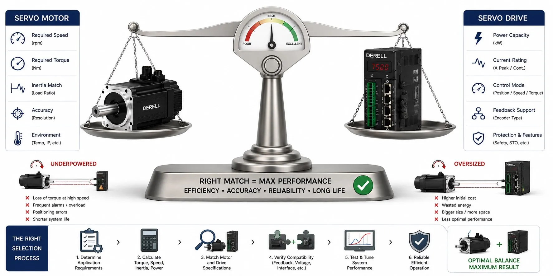
Choosing the right servo motor and drive
Start with the move, then choose the hardware. A power rating alone cannot describe what an axis needs: motors with the same rated power can have different torque, speed and inertia. Select the servo motor, drive and feedback as a compatible system. A matching brand name or kW label is not enough.
1. Write an axis specification
Define travel or rotation, cycle time, acceleration, deceleration and dwell. Include moving mass, rotating inertia, friction, process forces and gravity where relevant. Translate the load and transmission requirements to the motor shaft. Establish the required control mode and whether the machine needs coordinated axis motion.
The basic acceleration relationship is T = J × α: total inertia multiplied by angular acceleration. Add the torque needed to overcome the load. A shorter acceleration time raises the torque demand for the same speed change. Mass alone does not define a rotating load; its distance from the axis also affects torque and inertia calculations.
2. Check both peak demand and thermal duty
Peak torque covers the most demanding instant. RMS torque weights squared torque by time and helps assess the motor’s thermal duty. An arithmetic average misses the effect of high-torque intervals. This simplified motor-shaft torque profile illustrates the calculation; it is not a specification for a real machine.
| Cycle segment | Duration | Torque |
|---|---|---|
| High-torque interval | 0.2 s | 6 Nm |
| Lower-torque interval | 0.8 s | 2 Nm |
| Unloaded dwell | 1.0 s | 0 Nm |
TRMS = √[(6² × 0.2 + 2² × 0.8 + 0² × 1.0) / 2.0] ≈ 2.28 Nm. The peak requirement remains 6 Nm. The RMS result does not complete the selection. Check actual torque–speed operating points, permitted peak duration and cooling conditions. A dwell that holds a load needs its holding torque included; prolonged stationary loading also requires a separate thermal check.
3. Include the transmission and structure
A planetary gearbox changes the motor’s torque and speed requirements. With i = motor speed / load speed, reflected load inertia is Jload / i². A 5:1 reduction reduces that contribution to one twenty-fifth; motor and gearbox inertias must still be added. Review efficiency, backlash, stiffness and speed limits during gearbox selection. There is no single ideal inertia ratio for every servo axis.
Choose the motor construction around the mechanism; a frameless kit may suit embedded motion. High encoder resolution alone does not establish machine accuracy. Transmission backlash, structural deflection and mechanical vibration affect the final result.
4. Verify the exact motor–drive combination
Continuous and peak drive output current must support the required motor torque. Compare current ratings using the same RMS or peak convention. Verify supply voltage, winding choice, torque–speed curves, overload duration and thermal limits together. A larger drive does not remove the motor’s own limits.
Confirm the encoder or resolver interface, protocol, supply and wiring. Compare absolute and incremental feedback against startup position requirements and the intended homing procedure. On the controller side, check supported modes and update times as well as pulse/direction or EtherCAT connectivity. Drive configuration and auto-tuning follow hardware compatibility checks.
5. Separate holding brakes from braking energy
A standard motor holding brake primarily maintains a stationary axis. Do not select it as a service brake for repeated rapid stops, or assume it provides a safety function simply because it is fitted. For a vertical axis, assess holding capacity, engagement timing and the arrangements that prevent the load from falling.
Energy returned to the drive during deceleration is a different issue. A regenerative braking assessment determines whether the DC bus can absorb it and whether an appropriate braking resistor or line-regeneration solution is needed. Successfully stopping once does not establish the system’s ability to handle repeated braking cycles.