
What is Input reactor?
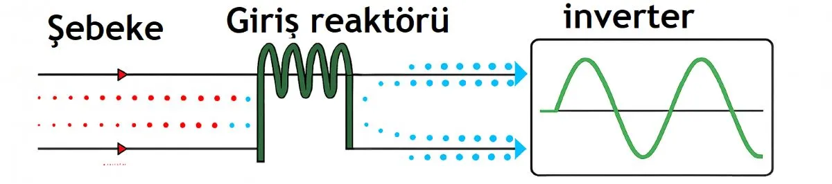
Adding useful impedance ahead of the drive
An input line reactor is an inductor connected in series with the AC supply of a variable-frequency drive. In a three-phase installation, each phase passes through a winding. The added impedance helps limit rapid current changes and rectifier current peaks, potentially reducing input-current distortion and the effects of some line-side transients.
Its role continues throughout operation; it is not simply a startup-current limiter. A reactor is not a voltage regulator, fuse or lightning-protection device. Its contribution depends on the disturbance and the complete installation.
The magnetic field opposes changes in current
As current changes, the winding’s magnetic field changes too. The induced voltage opposes that change, expressed ideally as vL = L × di/dt. This does not stop current from flowing; it makes a rapid change more difficult. Winding resistance and core losses also produce heat and voltage drop.
A rectifier feeding DC-link capacitors can draw short charging pulses from the mains. Additional inductance can reduce the peak and spread conduction over a longer interval. The useful distinction is a different current shape, not a universal reduction in the current required by the load.
Compare pulse height and pulse width
The upper diagram places the reactor ahead of the rectifier. Below, simplified triangular capacitor-charging pulses show the concept: the reactor example has a lower peak and a wider pulse. Equal areas represent the same transferred electric charge. These are teaching shapes, not measured waveforms or predictions for a specific drive.
Read the comparison correctly: the charts represent two separate installations. Current entering and leaving a reactor in the same series circuit is identical; a reactor does not absorb excess current and make it disappear. The actual waveform depends on supply impedance, load and drive design.
Harmonic reduction is different from reactive compensation
A less peaky rectifier current can reduce THDi and individual harmonics. The fifth and seventh are common characteristic components of a conventional three-phase six-pulse rectifier. A reactor does not make its input current perfectly sinusoidal or replace every harmonic-filter solution.
Lower current distortion can improve true power factor. That does not mean the reactor removes reactive power: the reactor itself draws inductive reactive power. Capacitor-based power-factor correction and harmonic-current mitigation are different tasks.
What a 3% or 5% rating tells you
3% and 5% are common catalogue options, not a mandatory range for every drive. A percentage rating refers to specified voltage, current and frequency conditions. Inductive reactance follows XL = 2πfL; the same winding does not have the same effect at every frequency or operating current.
For a simplified sinusoidal reference of 400 V line-to-line, 50 Hz and 20 A, phase voltage is approximately 231 V. An inductance of 1.1 mH per phase gives about 0.346 Ω and an inductive voltage of 6.9 V, approximately 3% of phase voltage. This does not mean the actual drive-terminal voltage always falls by exactly 3%; use the manufacturer’s rating definition.
More impedance brings a trade-off
Additional impedance can improve harmonic performance while reducing the voltage available to the drive. That matters on a weak supply or at full motor load. A larger percentage is not automatically a better choice. Include the drive’s existing DC-link choke and supply impedance in the assessment.
Selection involves input-current rating, overload duty, supply voltage, frequency, insulation, temperature and saturation behaviour. Motor kW and physical size alone are insufficient. Use the drive manufacturer’s approved rating and installation arrangement.
Power-up charging and motor acceleration are separate events
When mains power is applied, the DC-link capacitors charge. The drive’s precharge circuit manages that event; a line reactor does not replace it. During the motor’s acceleration ramp, the inverter and its control system manage motor current. Treating both events as one “heavy startup” problem can lead to the wrong remedy.
Identify which filter function you need
An EMI filter, EMC filter or RFI filter targets high-frequency interference. A line reactor does not remove the need for these components or suitable earthing. A zero-phase reactor has a different common-mode suppression function.
An output reactor or output filter is selected for the motor-side requirements. An input reactor does not turn PWM into a sine wave or resolve output dV/dt, long-cable effects or carrier-frequency issues. Use a component in both locations only where the manufacturer explicitly permits it.
References
Schneider Electric: line reactors and DC chokes
Schneider Electric: input-current harmonics and voltage drop
Schneider Electric: input and output reactor functions