
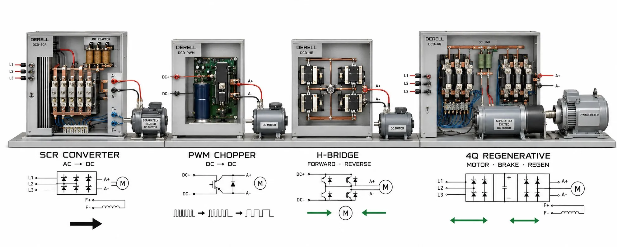
DC Drive Types: Understanding the Different Classifications
DC drives are classified by their power circuits, compatible motors, feedback arrangements and braking capabilities. The main power-stage distinction is between thyristor converters, which produce a controlled DC output from an AC supply, and transistor choppers, which regulate motor power by switching a DC supply. Terms such as digital, closed-loop and four-quadrant describe additional features.
A single DC drive can therefore be digital, thyristor-based, encoder-controlled and four-quadrant at the same time. Understanding these overlapping descriptions makes a specification far more useful than a simple list of drive names.
1. Thyristor Drives: Controlled Rectification from the AC Mains
An SCR, or thyristor, allows a converter to control when conduction begins during the AC supply cycle. Adjusting the firing angle changes the average DC voltage delivered to the motor armature. Different circuits are available for single-phase and three-phase supplies.
This architecture is used with industrial DC motors, including existing machinery where retaining the motor is part of a refurbishment plan. A separately excited motor also needs an appropriate field supply, which may be integrated into the drive or provided by separate equipment.
When assessing the operating characteristics of a DC drive, consider current ripple, supply harmonics and low-speed performance. The label “SCR drive” alone does not establish whether the unit can reverse the motor or return energy to the mains. Those capabilities depend on the converter arrangement and supported operating modes.
2. PWM Drives and Choppers: Related Terms, Different Meanings
A chopper describes a power-conversion circuit; PWM describes a switching technique. They should not be presented as mutually exclusive drive types. Many transistor-based DC choppers use pulse width modulation to regulate their output.
Power switches such as MOSFETs connect and disconnect the supply rapidly, allowing the controller to regulate average motor voltage and current. The DC source may be a battery, a power supply or a rectified DC link. Chopper technology is not restricted to low-voltage equipment.
A basic circuit may provide one-direction motoring, while a suitable H-bridge can control both voltage and current polarity. Its braking capability still depends on the complete circuit and control strategy. For dynamic performance, switching frequency is only one consideration. Motor inductance, current ripple, control-loop response and thermal limits also matter.
3. One-, Two- and Four-Quadrant Drives
Operating quadrants describe the relationship between shaft speed and motor torque. When speed and torque have the same sign, the motor delivers mechanical power. When their signs are opposite, electromagnetic torque opposes the motion and the motor converts mechanical energy into electrical energy.
A one-quadrant drive provides motoring in its permitted direction. Its power circuit may not support controlled opposing torque, so reducing the speed command does not necessarily produce a controlled deceleration under every load condition.
A two-quadrant drive supports two operating regions. Do not infer a particular reversing or regeneration function from “2Q” alone. Check the manufacturer’s quadrant diagram, voltage and current conventions, and motor connection requirements.
A four-quadrant drive can provide motoring and electrical braking in both directions when used in a suitable system. This is particularly relevant to reversing machinery and winding and unwinding duties.
| Speed | Torque | Operating state |
|---|---|---|
| Forward (+) | Forward (+) | Forward motoring |
| Forward (+) | Reverse (−) | Braking during forward rotation |
| Reverse (−) | Reverse (−) | Reverse motoring |
| Reverse (−) | Forward (+) | Braking during reverse rotation |
4. Regenerative Drives: Follow the Energy Path
Generating electrical energy at the motor and returning that energy to the mains are separate steps. A suitable regenerative thyristor system can feed power back into the AC supply. With a PWM controller, recovered energy may initially flow into the DC supply rail or DC link instead.
A battery system must be able to accept the resulting charge current, including any restrictions imposed by its battery management system. An ordinary DC power supply may be unable to absorb returned energy, allowing the supply voltage to rise. Where appropriate, a brake chopper and braking resistor provide a controlled way to dissipate excess energy as heat.
Four-quadrant motor control does not, by itself, guarantee mains regeneration. Any assessment of energy efficiency should account for how often braking occurs and where the recovered energy actually goes.
5. Analog and Digital Describe the Control Electronics
An analog drive implements its control functions mainly through analog circuitry. A digital drive uses processor-based control and may offer parameter storage, fault histories, configurable functions and communication interfaces.
Neither label guarantees a particular accuracy. Feedback quality, tuning, power-stage design and the machine itself all affect the result. A further distinction matters when reading specifications: a drive accepting a 0–10 V analog command can still be a fully digital controller internally. The command interface and control architecture are different characteristics.
For PLC integration, check the actual analog inputs, digital I/O and supported network options. “Digital drive” does not mean that every industrial communication protocol is available.
6. Open-Loop, Closed-Loop and Operating Modes
When discussing feedback arrangements, identify which loop is being described. A drive without a shaft-speed sensor may still have a closed current loop. Some units estimate speed from armature voltage and current information; that is different from measuring shaft motion directly.
A tachogenerator or encoder can provide measured feedback for a speed loop. However, speed feedback does not automatically provide position control. Positioning also requires suitable position information, a position loop and the necessary motion commands.
Voltage, current, speed and torque control are often operating modes within a drive rather than separate hardware families. When comparing control methods, remember that the relationship between armature current and torque depends on magnetic flux. Field weakening changes that relationship. Similarly, a “current-controlled” drive is not necessarily built around a current-source power topology.
7. Brushed DC, BLDC, Servo and VFD: Keep Motor Compatibility Clear
A BLDC motor needs electronic commutation. Although its controller may use a DC supply, the motor cannot simply be connected to a conventional brushed DC drive. Its phases must be switched in the appropriate sequence using suitable rotor-position information.
A servo system describes feedback-controlled motion. A brushed DC motor can form part of a servo system, while many industrial servo motors use other motor and drive architectures. “Servo” is therefore not simply another name for one type of DC converter.
A VFD controls compatible AC motors. Its internal DC link does not make it suitable for directly driving a brushed DC motor. When considering a conversion or retrofit, evaluate the differences between DC and AC drives together with the motor requirements.
8. Turn the Classification into a Useful Specification
Start DC drive selection with the motor type, armature voltage and current, and any field supply requirements. Then establish the available power source, continuous duty, short-term overload, speed range, required directions, stopping time and feedback needs. A kilowatt rating or the word “digital” is not enough to establish suitability.
A mechanism that runs in one direction and can coast to a stop has different requirements from an unwinder whose load drives the motor. The application’s load behaviour determines the necessary operating regions. Complete the specification by reviewing cooling, motor condition and the required protection functions.