
What is analog signal

How does a measurement become an electrical value?
Hello everyone. An analog signal represents a quantity using a continuous range of values. In industrial automation, information is commonly carried by a voltage or current level. For example, a sensor converts pressure into an electrical output, and a PLC reads that output to calculate the pressure in bar. The system can therefore answer “How much pressure is present?” as well as “Is pressure present?”
Analog does not mean that a signal must be sinusoidal or constantly changing. A steady 12 mA output at constant pressure is still an analog measurement signal. Microphone outputs, temperature-transmitter currents and position-sensor voltages are different applications of analog signals. Amplifiers increase signal level, while filters attenuate selected frequency components; analog systems do much more than read sensors.
Editor's note: Statements such as “analog is always less stable,” “digital signals cannot be distorted” or “analog carries more data” are not reliable general rules. Performance depends on circuit design, bandwidth, noise, resolution and connection conditions. A continuous analog representation does not give a real measurement system infinite accuracy.
The actual difference between analog and digital
An analog input measures the input level, whereas a conventional digital input detects an on/off state using defined thresholds. A pressure switch indicates whether a preset limit has been crossed; a pressure transmitter can report a value such as 3.2 bar. The choice between analog and digital inputs depends on the information the application needs. Digital communication can carry many numerical measurements and status values; it is different from a single on/off input.
Digital wiring is also subject to voltage drops, interference and timing errors. The receiver interprets physical levels as valid logic states; exceeding threshold or timing limits can cause data errors. In mixed systems, an analog-to-digital converter (ADC) digitizes a measurement, while a digital-to-analog converter (DAC) produces an analog output from a numerical command. A digital display therefore does not imply that the device has digital inputs and outputs.
PWM is not directly equivalent to a 0–10 V analog output. Information is carried by the duty cycle of pulses. A suitable filter or converter can produce an analog level, but a PWM output should not be connected to an analog input without checking compatibility.
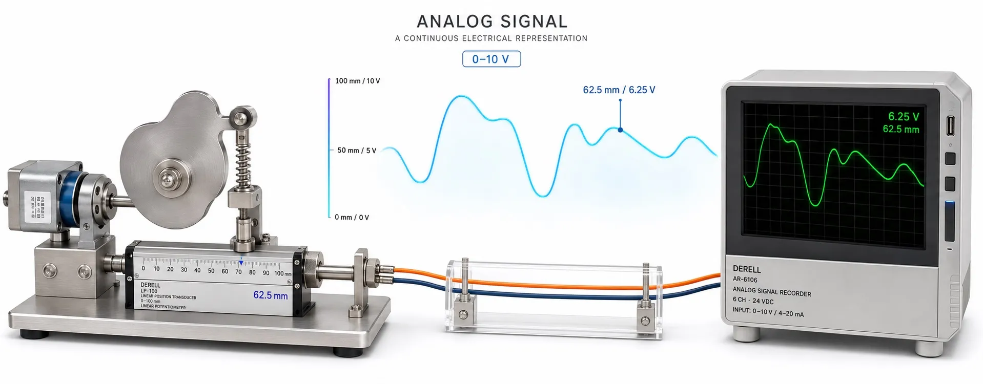
0–10 V, 4–20 mA and other common ranges
0–10 V voltage signal: Information is represented by the analog voltage between the signal and reference terminals. With a 0–10 V output sensor, 0 V may represent the lower measurement limit and 10 V the upper limit. A suitable potentiometer can also provide a speed command using a drive's own reference supply. Voltage-input performance depends on input impedance, source capability and the correct signal reference; an incorrect common connection can directly introduce measurement error.
4–20 mA current signal: Information is represented by the analog current flowing around the loop. With a 4–20 mA output sensor, the receiver measures that current. As long as the transmitter has sufficient operating voltage, the voltage drop caused by cable resistance does not directly change the measurement current. If the supply is insufficient or the total load is excessive, however, the transmitter loses current regulation and may fail to reach the upper measurement values. A current loop still has a voltage budget.
Live zero: The lower measurement limit is represented by 4 mA. For a 0–10 bar transmitter, 4 mA can mean 0 bar. A 0 mA reading from an open loop can therefore be distinguished from a valid lower-limit measurement. However, low current does not uniquely identify a broken wire; loss of power, connection problems and transmitter faults must also be considered. Diagnostic thresholds depend on the device's capabilities.
Other ranges include 0–20 mA, 1–5 V and ±10 V. A bipolar ±10 V signal can represent a directional speed or torque command in some drives, depending on configuration. When choosing between 0–10 V and 4–20 mA, consider distance, interference, response time and input compatibility together. A suitable analog-to-analog converter can match signal ranges; not every converter provides galvanic isolation.
PLC scaling: what pressure does 12 mA represent?
Consider a linear pressure sensor with a 4–20 mA output and a 0–10 bar measurement range. Calculate the measurement from the signal's position within its span:
Pressure (bar) = [(I (mA) − 4) / 16] × 10
This gives 4 mA = 0 bar, 12 mA = 5 bar and 20 mA = 10 bar. If the PLC reports a raw numerical value, the same principle applies: Measurement = lower measurement limit + [(raw value − lower raw value) / (upper raw value − lower raw value)] × measurement span. Take the raw endpoints from the module manual. In particular, an input configured for 0–20 mA may have a nonzero raw value at 4 mA. Handle out-of-range and fault values separately.
The same principle applies to speed commands. If a 0–10 V input is configured linearly for 0–50 Hz, 5 V commands 25 Hz. This does not establish an exact motor speed: pole count, slip, load and control method affect the result. In PLC-based PID control, feedback must also be scaled into the correct engineering units. An incorrect range can cause even a correctly tuned controller to behave incorrectly.
Resolution, accuracy and sampling are different
Resolution concerns the steps available during digitization. An ideal 12-bit ADC provides 4096 codes; over a 0–10 V full-scale range, one code has a voltage width of approximately 2.44 mV. This is not the total measurement error. Accuracy describes closeness to the actual value, while repeatability describes agreement between results under the same conditions. Sensor error, offset, gain error, temperature drift and noise must be considered together.
Sampling rate specifies how often the signal is digitized. For ideal reconstruction of a band-limited signal, the sampling frequency must exceed twice the highest signal frequency. Practical systems require additional margin and an appropriate low-pass filter before the ADC. A slow level measurement and a fast vibration measurement do not have the same hardware requirements. Excessive software smoothing also adds delay and can slow the control response.
Wiring and interference: why a correct signal reads incorrectly
Electromagnetic interference near motor cables, contactors and drives can introduce unwanted components into a measurement signal. Separating signal and power wiring appropriately, using twisted pairs and terminating shields according to the manufacturer's guidance improve noise immunity. Whether a shield should be connected at one end or both ends should not be treated as a universal rule for every installation.
Differences in ground potential can create measurement errors. Within its permitted common-mode voltage range, a differential input can reduce common-mode effects; it is not equivalent to galvanic isolation. If isolation is needed, verify that the module or signal isolator actually provides it. Although 4–20 mA has advantages in many field applications, it is not completely immune to interference.
Field checks: start at the terminals, then check the software
First confirm that the transmitter output and receiver input use the same signal type and range. Check any hardware selector as well as the menu configuration. With a suitable multimeter, measure voltage in parallel across the relevant terminals. Measure current in series using an appropriate mA measurement arrangement; do not connect a meter in current mode across a voltage source. For a two-wire loop, also check the power supply and active/passive input compatibility.
A loop calibrator can apply 4, 12 and 20 mA to check the lower, middle and upper points, with unexpected machine movement prevented. If the terminal signal is correct but the displayed value is wrong, investigate input configuration and scaling. If the terminal signal is also wrong, check the transmitter, supply, load and wiring. This approach identifies which part of the measurement chain is introducing the error.
Related equipment and further reading
Analog signal controllers, variable frequency drives, sensors and analog input/output arrangements.
Technical references
Analog Devices — AN-1312: 4–20 mA measurement and current-loop operating conditions
Texas Instruments — TIDA-01633: Reference design for voltage/current inputs and outputs
Tektronix — ABCs of Probes: Logic thresholds, probe loading and signal measurement
NI — Acquiring an analog signal, sampling and aliasing
NI — Field wiring, reference connections and noise considerations for analog signals