
What is analog input in controller?
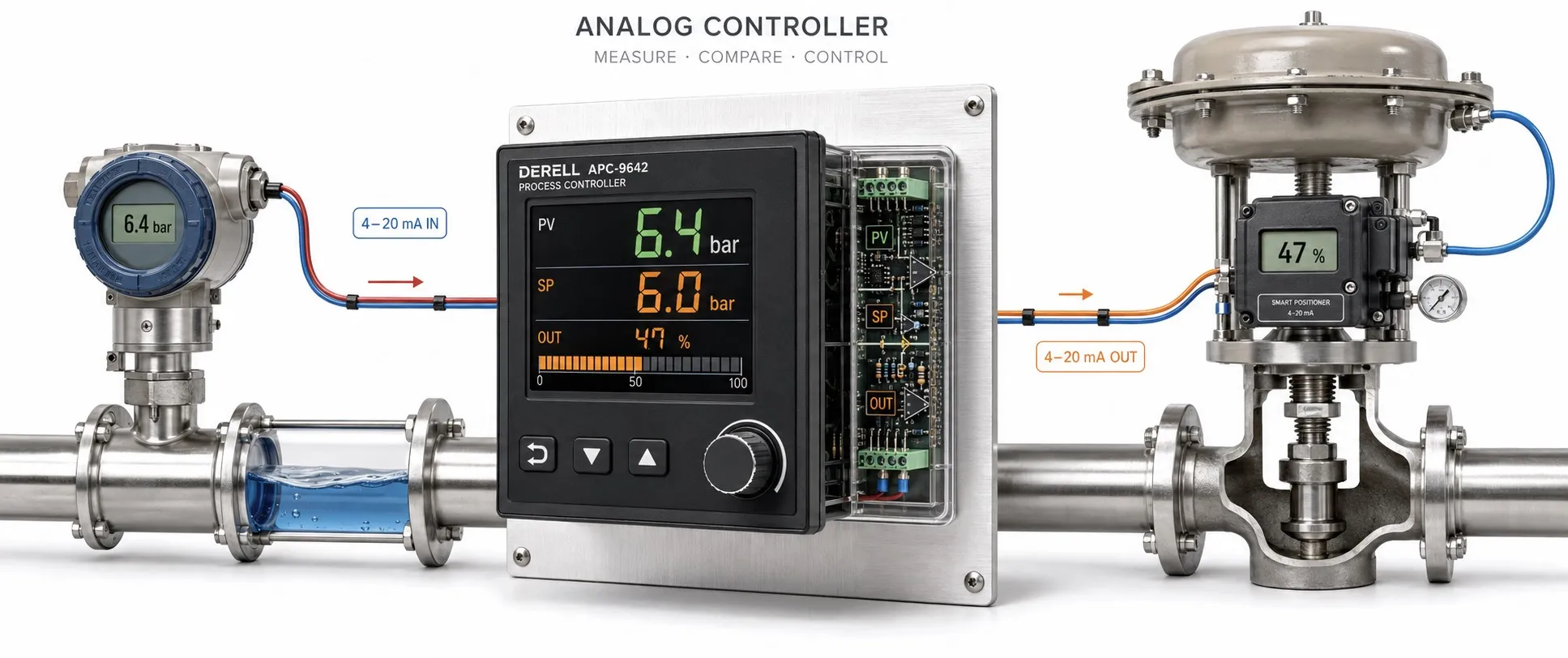
From a measurement signal to a control decision
The term analog controller is often used for instruments that receive temperature, pressure or level information through an analog input. The instrument may scale the analog signal into engineering units, monitor a limit or adjust an output to maintain a target value. However, using an analog input and implementing control entirely with analog circuitry are different concepts.
Editor's note: An instrument with a digital display can accept a 4–20 mA analog input and process the measurement with a microprocessor. Conversely, an entirely analog control circuit does not necessarily require an ADC. Input type, internal processing and output type must be assessed separately.
Analog processing and digital processing
An entirely analog controller can perform comparison and correction using components such as amplifiers, resistors and capacitors. In a microprocessor-based controller, an analog-to-digital converter (ADC) turns the measurement into numbers for processing. When an analog output is required, digital-to-analog conversion (DAC) may be used. A relay-output or pulse-output model must not be assumed to provide an analog output.
What do 4–20 mA and 0–10 V represent?
Sensors with a 4–20 mA output transmit measurement information as current. 4 mA represents the lower range value and 20 mA the upper range value. The lower physical value is not always zero: on a 20–120 °C scale, 4 mA represents 20 °C. 0 mA is not the normal lower measurement value; possible causes include an open loop or a supply fault.
Sensors with a 0–10 V output transmit information as voltage. Receiver input impedance, reference connections and cable effects matter. Changing a menu setting alone does not convert between 0–10 V and 4–20 mA. The input hardware, wiring and scaling configuration must support the signal type.
Why does 12 mA represent 50 percent?
Consider a pressure transmitter measuring 0–100 bar with a linear 4–20 mA output. The usable current span is 16 mA. An input of 12 mA is 8 mA above the lower endpoint, so (12 - 4) / 16 = 0.50 and the displayed value should be 50 bar. With the same 0–100 bar engineering scale on a 0–10 V input, 5 V also represents 50 percent.
The diagram compares scaling on two separate signal ranges; it is not a wiring diagram connecting current terminals to voltage terminals. A measurement at 50 percent does not necessarily require a 50 percent output. The control output depends on the setpoint, control action and algorithm.
Indication, alarms and closed-loop control differ
An indicator may simply display the measurement. An alarm function may change a contact state when a configured limit is crossed. A controller compares the measurement with a setpoint and adjusts its output. Returning the measurement through feedback creates a closed control loop. An analog input alone does not establish that an instrument provides all these functions.
With on-off control, the output switches according to defined conditions; hysteresis reduces repeated switching near the threshold. A PID controller calculates correction from the error and its behavior over time. A sensor reaching 70 percent is not a universal relay switching rule.
Select inputs and outputs independently
A controller with a 4–20 mA input may have relay, SSR drive pulse, 0–10 V or 4–20 mA outputs, depending on the model. An SSR drive pulse is not itself a load-power output. Check the required output type and switching capacity separately for a contactor coil, heater or valve.
Pt100 sensors and thermocouples also provide analog measurements, but they cannot simply be wired as 4–20 mA sensors. They require a compatible sensor input or an appropriate transmitter. Input compatibility is not established merely because both devices measure temperature.
What determines accuracy and correct field wiring?
It is incorrect to assume that analog systems are always more accurate or that more bits automatically mean greater measurement accuracy. Sensor error, input circuitry, resolution, noise, temperature drift and calibration must be assessed together. Filtering can stabilize the reading, but excessive filtering can delay the control response.
During installation, check two-, three- or four-wire sensor arrangements, active/passive interface compatibility, loop supply, input burden and isolation. In a current loop, voltage drops across wiring and the input must leave enough voltage for the transmitter. Follow the manufacturer's shielding and grounding instructions; a 4–20 mA circuit is not immune to every noise source or ground loop.
When comparing analog-signal controllers, consider the input range, engineering scale, control method and output type together. Output behavior after a sensor fault, alarm action, supply voltage and panel mounting also form part of the selection.
Related analog topics: Analog signal fundamentals, the role of an analog input and analog inputs versus outputs explain the basic interfaces. The difference between analog and digital inputs and 0–10 V and 4–20 mA ranges help with interface selection.
Connected applications: Temperature controllers, pressure transmitters and humidity controllers address different measurement tasks. Explore PID control and variable-frequency drives to see how a measurement can be used to regulate a process or motor.
Sources
Analog Devices: analog and digital approaches to PID control
Texas Instruments: digitizing a 4–20 mA input with an ADC
NI: 4–20 mA current loops, supply requirements and isolation
NI: the distinction between resolution and measurement accuracy
OMEGA: input and output options in microprocessor-based controllers