
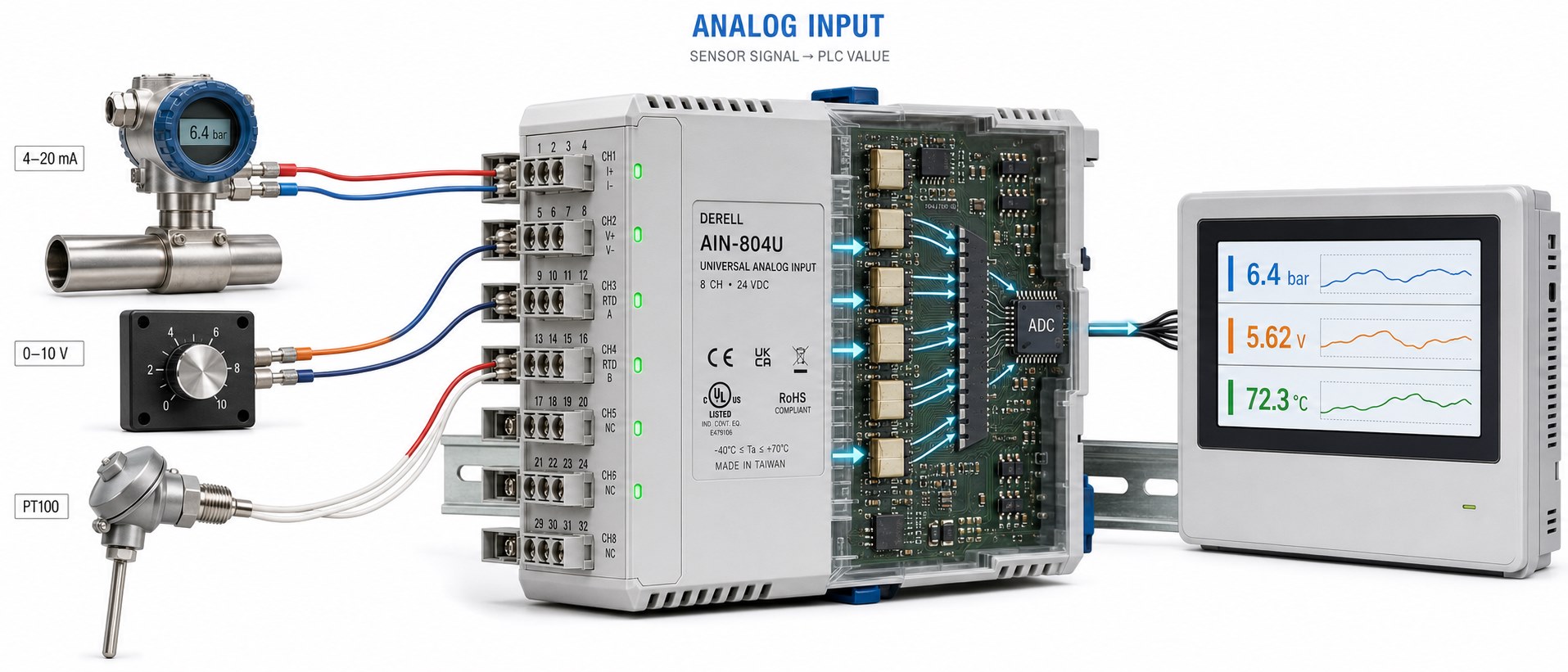
What is an analog input?
An analog input is a channel that measures an electrical signal whose magnitude represents a value. That value might be pressure, temperature, tank level or a requested operating speed. It is the receiving side of an analog signal interface, found in many PLCs, variable frequency drives, temperature controllers and process indicators. The available input types depend on the device; an analog input is not automatically compatible with every sensor.
The useful distinction is between a state and an amount. A pressure switch tells a digital input whether a threshold has been reached. A suitable pressure sensor supplies a varying signal that lets the controller distinguish, for example, 3.2 bar from 7.6 bar.
Match the input to the signal
Voltage inputs commonly accept ranges such as 0–10 V, 0–5 V or ±10 V. The receiver measures signal voltage relative to its specified reference terminal. A 0–10 V sensor can provide a measurement, while a potentiometer can provide an operator's speed setting. A sensor's supply voltage is separate from its output signal.
Current inputs often use 0–20 mA or 4–20 mA. With 4–20 mA sensors, the measured value is carried by the loop current. Current signalling is widely used for longer cable runs and electrically noisy installations. It still needs correct wiring, sufficient supply voltage and an acceptable total loop load.
Direct sensor inputs use different measurement circuits. A Pt100 RTD or NTC thermistor changes resistance; a thermocouple produces a small voltage. Neither is a direct substitute for a standard 0–10 V or 4–20 mA source. The RTD and thermocouple comparison explains the sensor differences, but the receiver must also support the selected sensor type. A temperature transmitter can convert the sensor response into a standard process signal.
A load cell typically needs a bridge input or a weighing transmitter. A terminal marked “AI” identifies an analog input, not a universal sensor connection. Check its supported ranges and wiring before making the connection.
From an electrical signal to an engineering value
In a digital controller, the input circuitry conditions the signal and an analog-to-digital converter (ADC) produces a numerical code. Scaling then assigns that code a useful unit: bar, °C, percent or another process quantity. A controller built entirely with analog circuitry does not necessarily use an ADC.
A continuous signal does not give the receiver unlimited precision. An ideal 12-bit ADC has 4,096 levels across its full conversion range. For a 0–10 V range, the theoretical step is approximately 2.44 mV. Resolution is not accuracy: sensor error, input electronics, noise and temperature effects also influence the result.
Worked example: a 0–10 bar transmitter
Assume the transmitter is configured so that 4–20 mA corresponds linearly to 0–10 bar. The current span is 16 mA, and its midpoint is 12 mA. The pressure calculation is:
Pressure (bar) = [(Current (mA) − 4) / 16] × 10
| Input current | Percentage of span | Pressure |
|---|---|---|
| 4 mA | 0% | 0 bar |
| 8 mA | 25% | 2.5 bar |
| 12 mA | 50% | 5 bar |
| 16 mA | 75% | 7.5 bar |
| 20 mA | 100% | 10 bar |
4 mA is a valid reading at the bottom of the configured range. A current close to zero may indicate a broken wire or loss of power. The transmitter and input module documentation defines the diagnostic thresholds and response. A failed signal must not simply be treated as a valid zero-pressure measurement.
The controller's raw numerical representation is a separate matter. Some Siemens modules configured for 4–20 mA represent 4 mA as 0 and 20 mA as 27648. Other devices use different conventions. Always identify the raw endpoints before applying a scaling function.
A measurement input or a command input?
The same signal format can serve either purpose. An analog sensor sends a measurement; another controller's analog output can send a requested speed or valve position. If a drive maps 0–10 V to a 0–50 Hz frequency reference, 5 V requests 25 Hz. It does not measure the motor's actual speed. This distinction matters when designing analog input and output connections.
In pressure control, the input can supply feedback. In temperature control, it provides the process value. A humidity sensor with a compatible analog output follows the same principle. The controller compares the measured value with the setpoint and adjusts its output.
What to check during commissioning
Verify the electrical range first. The sensor output, any hardware selector and the input configuration must agree. Selecting 0–20 mA for a 4–20 mA transmitter gives incorrect engineering values unless the scaling accounts for the different endpoints. Do not connect a 24 V supply to a 0–10 V measurement input; it may exceed the input's permitted limits.
Check who powers the loop. Active and passive current interfaces require different wiring arrangements. A two-wire transmitter and a separately powered transmitter cannot be assumed to use the same circuit. Identify the functions of AI−, COM or M from the wiring diagram. A signal reference is not automatically the same connection as protective earth.
Investigate unstable readings before increasing filtering. Route signal wiring with suitable separation from motor and power cables, and follow the manufacturer's shielding and grounding instructions. Choose sampling and filtering settings that suit the process. More filtering may steady the displayed value, but it can also delay the control response.