
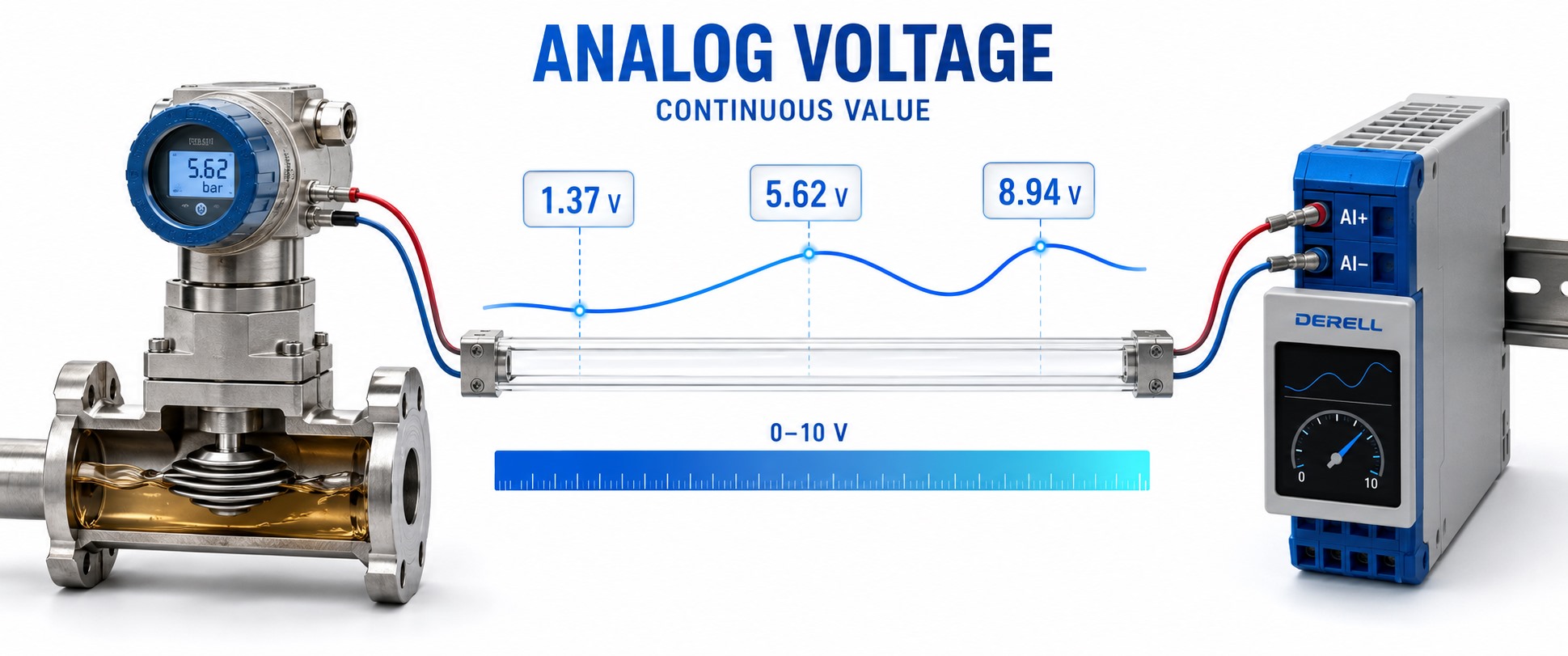
Analog voltage: information carried by a level
When a controller reads an analog voltage, the voltage level carries information. A pressure transmitter might use 0 V for the bottom of its range and 10 V for the top, with intermediate voltages representing intermediate pressures. The receiver needs to know how much voltage is present, rather than just whether a signal is on.
An analog signal is described over a continuous range of values. It can remain steady when the measured quantity is steady: analog does not mean constantly moving. Real hardware still has limits set by noise, accuracy and bandwidth, so a continuous signal is not an infinitely precise measurement.
A DC signal can change
A common misconception is that DC voltage must have a fixed value. A 0–10 V sensor output can rise from 2 V to 8 V and fall again while retaining the same polarity. That is a changing DC level. Ripple or other unwanted variation can also be superimposed on it.
The illustration compares this with an AC waveform that crosses zero. The orange dots follow the signal values. The upper trace takes positive and negative values; the lower trace stays positive throughout its 2–8 V range. Motion is deliberately slow for teaching and does not represent an actual mains or sensor frequency.
Start restarts the movement; Stop ends it. The traces illustrate signal behaviour rather than providing live measurements. AC/DC describes voltage behaviour; analog/digital describes how information is represented.
What does a reading of 5 V tell you?
Without the configured measurement range, not enough. A linear 0–10 V output representing 0–100 °C gives 50 °C at 5 V. The same electrical range representing 0–16 bar gives 8 bar at 5 V. The voltage does not identify its engineering unit.
For a linear 0–10 V mapping: Measured value = lower limit + (voltage / 10 V) × (upper limit − lower limit). Use this relationship for a 0–10 V sensor configured to provide that linear output. It does not describe every raw sensor signal. Other ranges, including ±10 V, 0–5 V and 1–5 V, require their own scaling.
Feedback signals and command signals
On the measurement side, an analog input makes a voltage available to a PLC program as a measured value. Sources may include a humidity transmitter, a pressure transmitter or a position potentiometer. A bare Pt100 element uses a different electrical interface and cannot be treated as a ready-made voltage output.
On the command side, an analog output can send a speed reference to a variable frequency drive. If its reference is configured as 0–10 V = 0–50 Hz, 6 V requests 30 Hz. The reference alone does not establish the actual shaft speed. Drive settings and motor behaviour also matter. A potentiometer can provide a manual voltage reference when connected to a suitable interface.
Why an NTC needs a measurement circuit
An NTC thermistor changes resistance with temperature; it does not generate a voltage by itself. In a powered voltage divider, that resistance change produces a voltage change. Whether the voltage rises or falls with temperature depends on the circuit arrangement.
The response is generally nonlinear, so temperature conversion needs the appropriate sensor characteristic. Keep three things distinct: the sensing element, the measurement circuit and a transmitter with a standard voltage output. A transmitter can condition the resistance measurement and map it onto a range such as 0–10 V.
Conditioning and conversion
An amplifier can provide voltage gain, while a buffer can reduce loading of the source. A filter attenuates unwanted frequency components; it does not remove every possible disturbance. An analog-to-digital converter samples the voltage and represents it with numerical codes. A DAC produces an analog output from a digital value.
Analog current and analog voltage are different interfaces. Adapting a 4–20 mA output to a voltage-only receiver requires suitable analog-to-analog conversion. A PWM output is another case: changing the pulse duty cycle does not automatically produce a smooth analog voltage. Appropriate filtering and interface circuitry may be needed.
Before blaming the sensor
Check the input configuration and reference. Is the receiver in voltage mode? Does it expect 0–10 V or ±10 V? Which COM or reference terminal defines the measurement? Signal reference and protective earth are different functions. Follow the device’s analog I/O connection diagram.
Check loading and interference. A receiver can pull down the source voltage if the impedances are unsuitable. Reference potential differences, wiring faults and interference from drive wiring can also affect the result. A multimeter helps check a slowly varying level; an oscilloscope is more useful for fast changes or ripple. Compare the electrical reading with the controller’s scaled engineering value.