
What is analog current?
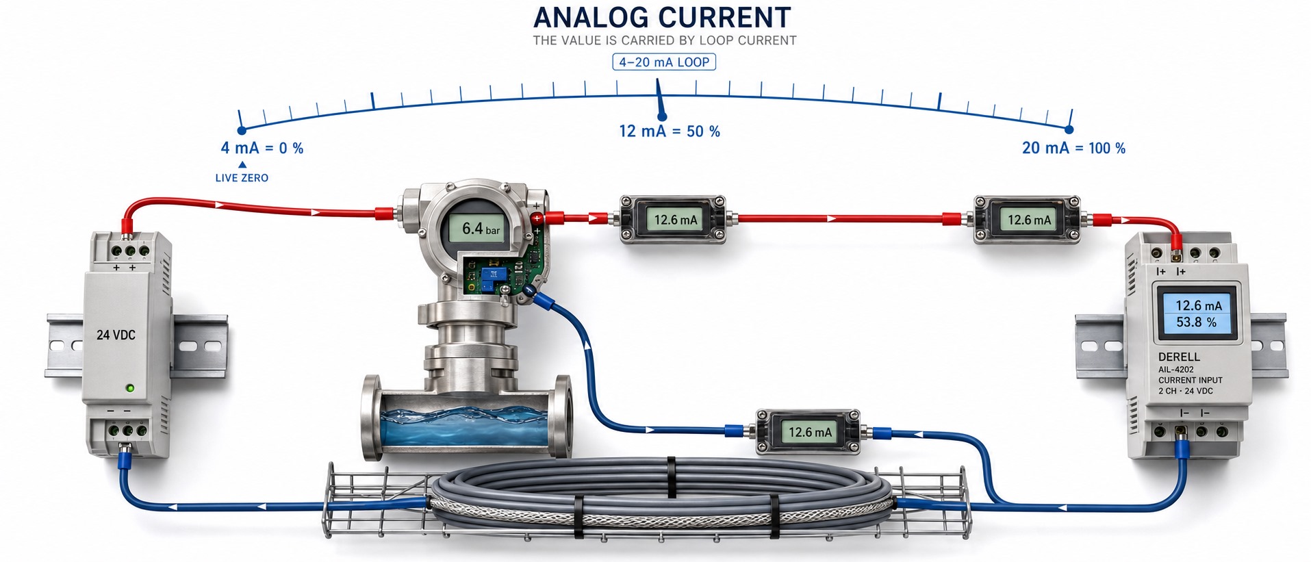
What is analog current?
Hello friends, an analog current signal carries information through the magnitude of an electric current. A pressure sensor, for example, can represent its measurement with a current between 4 and 20 mA. Here, current does more than supply power: its value represents the measured quantity. The basic unit of current is the ampere; 1 mA = 0.001 A.
An analog signal can represent intermediate values. However, “analog” does not mean constantly changing: When the measurement is steady, its signal can remain steady too. Analog current is not a separate kind of electricity; the term describes how current is used to convey information.
How does a 4–20 mA signal work?
In industry, 4–20 mA analog sensors can send measurements to a PLC or an analog signal controller. With standard linear, increasing scaling, 4 mA represents the lower measurement limit and 20 mA represents the upper limit. The span is 16 mA, so the midpoint is 12 mA.
Example: For a pressure transmitter configured for 0–10 bar, 4 mA = 0 bar, 8 mA = 2.5 bar, 12 mA = 5 bar, 16 mA = 7.5 bar, and 20 mA = 10 bar. Thus, 12 mA represents 50% of the measurement span. Dividing 12 by 20 gives 60%, but that is not the correct process percentage.
Scaling formula: Measured value = lower limit + [(I − 4) / 16] × (upper limit − lower limit). I must be expressed in mA. This formula applies to linear, increasing scaling over 4–20 mA; reverse or custom scaling requires a different mapping.
4 mA is a live zero: Current still flows at the bottom of the measurement range. This helps distinguish a valid minimum measurement from an out-of-range value such as 0 mA. However, 0 mA does not identify the fault by itself: A broken wire, missing supply, or device failure may be responsible. Interpret alarm thresholds using the device documentation.
Is analog current AC or DC?
It can be either. Common industrial 4–20 mA loops use DC signalling: The current stays in one direction while its magnitude changes with the measurement. Increasing from 6 mA to 14 mA does not make it AC. Alternating current reverses direction, and an analog waveform can also carry information in that form. Analog does not automatically mean AC, and DC does not automatically mean a constant value.
A transmitter may process its measurement digitally while providing an analog 4–20 mA output. Likewise, a PLC's analog-to-digital converter (ADC) turns an analog input into numerical data. The conversion has finite resolution, so an analog input does not provide unlimited precision.
Analog current versus analog voltage
Analog voltage represents information through voltage level; analog current represents it through current level. 0–10 V and 4–20 mA are common examples. Voltage inputs typically have high input resistance, whereas current inputs are designed to measure loop current. Check the input mode and specifications before connecting either signal.
A properly designed current loop tolerates wiring voltage drops well. However, cable length is not unlimited. The supply must cover the voltage required by the transmitter, wiring, and receiver. If the power supply cannot provide sufficient voltage, the transmitter may fail to deliver the requested current, particularly near the upper measurement limit.
Using Ohm's law, 4–20 mA through a suitable 250 Ω precision resistor produces 1–5 V: 0.004 × 250 = 1 V and 0.020 × 250 = 5 V. This approach requires compatible receiver voltage limits, input resistance, resistor tolerance, and loop load capacity. A current input may already contain a sensing resistor; do not add another resistor without checking the circuit.
Where is analog current used?
Analog current can carry measurements or commands in pressure control, temperature control, level control, and flow control. In PLC-based PID control, the measurement is compared with a setpoint. A compatible drive can also accept an analog current signal as a speed reference. The command signal is not the motor's power current; a 4–20 mA signal does not directly power the motor.
Wiring, measurement, and troubleshooting
Check the input type and wiring diagram first. A PLC channel may be configured for 0–20 mA, 4–20 mA, or voltage. A two-wire loop-powered transmitter is wired differently from a separately powered device. Match the DIN rail power supply, active/passive input arrangement, and polarity using the equipment documentation. Follow the system's EMC requirements for grounding and cable shielding.
For direct mA measurement with a multimeter, use the correct current range and connect the meter in series with the loop. Never connect a meter in current mode directly across a power supply; it can create a short circuit. De-energize before changing wiring and consider how opening the loop will affect the process. See current measurement and multimeter input terminals for further guidance.
If the reading is incorrect, check the signal range, scaling, supply, polarity, and wiring together. If the measured current is correctly 12 mA but the displayed pressure is wrong, check the PLC or indicator scaling before assuming the sensor has failed.
Technical references: NI: 4–20 mA fundamentals · Analog Devices: current loop measurement · Fluke: measuring loop signals