
Common issues and fixes for DC drives?
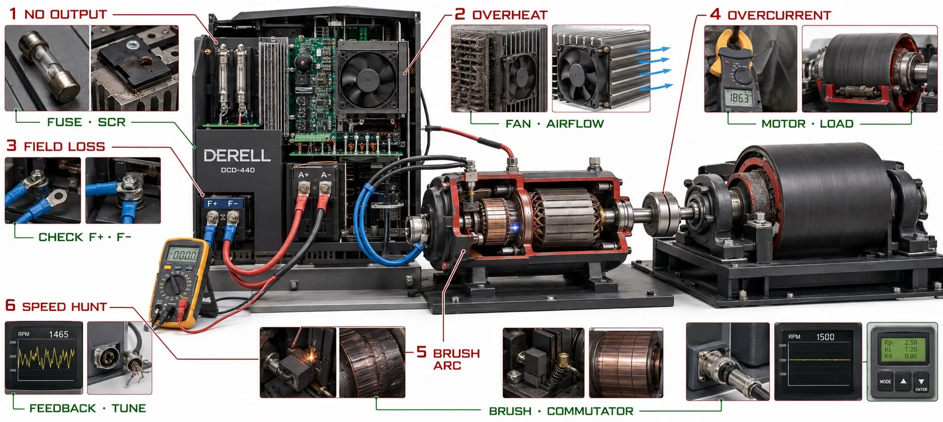
What are the most common DC drive problems and their solutions?
Hello, DC control enthusiasts,
A DC drive fault does not necessarily mean that the drive's electronic board has failed. Motor brushes, the commutator, field supply, speed feedback, mechanical load or commands from the PLC can produce similar symptoms. A stopped motor is not proof of a faulty drive. The protection system may have stopped the motor because it detected a problem elsewhere.
This guide mainly covers industrial drives for brushed DC motors. In a separately excited motor, the armature and field circuits must be assessed separately. A permanent-magnet DC motor has no separate field winding, so field-supply checks do not apply to it. BLDC motors use a different electronic commutation arrangement.
1. The motor will not start: Is the command missing, or is power unavailable?
Symptom: The drive display is on, but the motor does not turn after a start command. An active display does not prove that the motor power circuit is also energized.
Check in order: Review active faults, local/remote selection, run permissives and the speed reference. Then assess the safety chain, contactor feedback and, where fitted, the conditions required to release the mechanical brake. Check the field supply on separately excited motors. If the control conditions are correct, inspect the power supply, specified fuses and motor connections against the manufacturer's wiring diagram.
A useful clue: If the monitored armature current is close to zero, investigate missing commands, missing permissives or an open circuit. If current rises but the shaft does not turn, consider a jammed load, an unreleased brake or a motor problem. These observations help narrow the investigation; they do not establish the cause on their own.
2. Motor speed fluctuates or hunts
Possible causes: An unstable speed reference, an intermittent potentiometer, a loose encoder connection, a tachogenerator problem, mechanical backlash or unsuitable speed-controller settings can produce similar symptoms.
Check: Compare the speed reference, actual speed and armature current over the same period. If the reference also fluctuates, investigate the command source first. If the reference is steady but speed varies, assess speed feedback, the mechanical load and the control loop. A loose coupling or interrupted feedback signal cannot be repaired by changing a gain parameter. After checking the hardware, back up the settings and follow the manufacturer's tuning procedure.
3. The motor runs unloaded but cannot deliver enough torque under load
The basic relationship: Electromagnetic torque in a brushed DC motor can be described approximately by T = k × Φ × Ia, where Φ is magnetic flux and Ia is armature current. If flux is insufficient, simply trying to increase current is not the correct remedy.
Check: Assess the motor nameplate data, the drive's current limit, the field supply and the mechanical condition of the load together. Poor brush contact or increased connection resistance can also affect performance. Reduced available torque in the field-weakening region may be part of the intended operating characteristic. Before raising a current limit, verify the permitted ratings of the motor, drive and machine. Correct DC drive selection must account for the actual load requirements.
4. The motor or drive overheats
Identify what is hot first: The motor frame, the drive heatsink and an electrical connection can overheat for different reasons. Motor heating may result from excessive load, inadequate ventilation at low speed or mechanical friction. For the drive, investigate fan failure, clogged filters, high cabinet temperature or restricted airflow.
Remedy: Restore proper cooling and correct unsuitable load conditions; verify any separately powered motor fan. If heating is concentrated at one terminal or cable lug, inspect the connection and its contact surfaces. Adding an arbitrary heatsink does not remove the cause of excessive current or a poor connection.
5. Field loss and unexpected acceleration
The field circuit establishes the main magnetic flux in a separately excited DC motor. A weakened or lost field can cause loss of torque and, depending on operating conditions, a dangerous increase in speed. Controlled field weakening during normal operation is different from an accidental loss of field.
Check: Assess the field supply, field-circuit continuity and the drive's field-current monitoring according to the manufacturer's instructions. For unexpected acceleration, also investigate speed-feedback direction, scaling and mechanical coupling. Do not operate the machine with field-loss or overspeed protection disabled. See the related guide to DC drive protection mechanisms.
6. Brush sparking, commutator discoloration or erratic running
Possible causes: Worn or unsuitable brushes, inadequate spring pressure, brushes sticking in their holders, an uneven commutator surface, overload or motor commutation problems should be investigated. Heavy, continuous arcing must not be treated as normal.
Remedy: After stopping and safely isolating the motor, inspect brush length, free movement, connections and commutator condition using the motor manufacturer's maintenance instructions. Replacing the brushes alone will not solve every problem. Do not apply arbitrary abrasives, oil or contact spray to the commutator. Surface damage and suspected winding faults require assessment by a motor maintenance specialist. Regular DC drive and motor maintenance helps identify deterioration before it becomes a breakdown.
7. Overcurrent trips or blown fuses
Timing is informative: A fault during initial acceleration may be associated with an unreleased brake, a jammed mechanism or an acceleration ramp that is too short for the load. A fault during operation may be associated with a sudden load increase, a motor or cable problem, or a power-circuit failure.
Remedy: Record current and speed at the time of the fault. Do not fit a larger fuse before investigating the motor, cabling and mechanical load. Fuse selection depends on the required type and protection coordination, not just the current rating. Before insulation-resistance testing a motor or cable, disconnect it from the drive electronics and follow the manufacturer's test procedure.
8. The motor turns in the wrong direction or trips during reversal
Possible causes: The command sign, wiring arrangement, feedback direction or drive operating capability may not match the application. DC drives do not all provide the same reversing and regenerative-braking capabilities.
A technical detail: In a conventional brushed DC motor, torque direction depends on the relative directions of armature current and field flux. Reversing both may leave the rotation direction unchanged. This is not an instruction to swap connections as an experiment. Direction and feedback checks must be performed together using the drive's commissioning procedure. The guide to different types of DC drives explains why the power-circuit arrangement matters.
9. The drive stops intermittently or trips during braking
Check: Establish whether the fault occurs during acceleration, at steady speed, during deceleration or after the system has warmed up. Assess the mains supply, auxiliary supply, motor temperature, contactor state and external fault inputs at the same time.
For deceleration faults, load inertia, the stopping ramp and how the drive handles returned energy are relevant. A thyristor drive capable of returning energy to the mains has different braking requirements from other DC drive arrangements. Adding a braking resistor is therefore not a universal solution for DC drives. Verify which braking method the installed hardware supports.
10. Electrical interference and PLC communication problems
If interference is suspected: Check whether the problem coincides with contactor operation, another drive starting or a load change. Review the routing of power cables and low-level reference or feedback cables, shield connections and equipotential bonding against the manufacturer's instructions. There is no single shield-connection rule that applies to every cable.
If communication is suspected: First check cabling, connectors, device addresses, communication settings and protocol-specific termination. Even with an active connection, an incorrect control word, data mapping or reference scale can prevent the expected operation. The guide to DC drive and PLC integration covers the control interface. A firmware update should not be the first experiment: consider it only when it addresses the relevant issue, compatibility has been confirmed and a backup is available.
What information should you provide to a service technician?
The drive make and model, motor nameplate data, exact fault code, operating stage when the fault occurs and the most recent change all help diagnosis. Unloaded and loaded behavior, the difference between speed reference and actual speed, and a parameter backup are also useful. A record such as “armature current reaches its limit and speed falls as load increases” is more informative than “it sometimes stops.”
Manufacturer's manual example: ABB DCS550 Manual — Safety instructions and Fault tracing. The manual treats field undercurrent, speed feedback, overspeed, motor stall, temperature and communication faults separately. Its model-specific fault codes and settings must not be applied directly to other drives.
This article provides general technical information and does not replace service instructions for the specific drive and machine. You may share this article with attribution to our website.