
What are the main components of a robot?
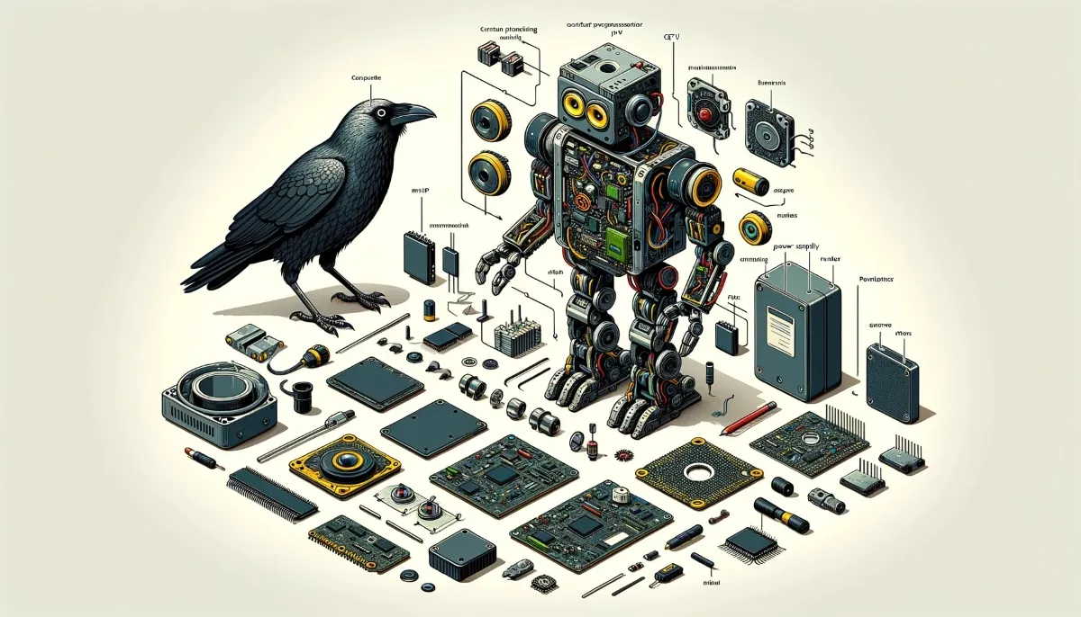
A robot brings together a mechanical structure, actuators, a control system, sensors and a power supply. Software coordinates these parts, while tools, communication interfaces and protective equipment depend on the job. An arm, a camera and artificial intelligence are not universal requirements. A warehouse vehicle and a welding arm have different hardware, but both need a way to produce and control movement. Our guide to robot types explains these different arrangements.
1. Structure: the hardware that carries the load
An arm uses a base, links and joints. A mobile platform uses a chassis, wheels or tracks, and sometimes suspension. Reach, stiffness and load capacity determine which tasks the structure can handle. More axes provide additional movement options; they do not automatically mean greater accuracy or a higher payload. The intended industrial application shapes the mechanical design.
2. Actuators and transmission: turning energy into motion
An actuator produces physical movement. Servo motors are common in robot arms, while other designs use pneumatic or hydraulic actuators. Gears, belts and planetary gearboxes transfer movement to the mechanism at a suitable speed and torque. A gearbox trades speed for torque; it does not create energy. Sizing a joint also requires attention to acceleration and the load's distance from the joint, rather than weight alone.
3. Controller, drive and motor: who does what?
These three components have distinct responsibilities. The controller runs the task and coordinates the axes. A servo drive manages the motor's electrical operation. The motor produces mechanical output. A manufacturer may package several functions together, but the distinction still matters.
| Component | Job | Arm example |
|---|---|---|
| Controller | Calculates targets and coordinates motion. | Determines where the arm should move and how fast. |
| Drive | Controls electrical power delivered to the motor. | Regulates motor current using commands and feedback. |
| Motor | Converts electrical energy into mechanical motion. | Produces torque to turn a joint. |
Control is often shared across layers: a drive can regulate current while a controller plans the path. Feedback functions such as a speed loop help the motion follow its target. A PLC may coordinate the robot with a conveyor or another machine without directly controlling every robot joint.
4. Sensors: checking what actually happened
An encoder or resolver provides axis feedback. An inductive sensor can detect a metal part; a laser sensor can measure distance. Vision, force sensing and vacuum monitoring may be added when the task requires them. Knowing the joint position does not prove that the gripper holds a part. That needs suitable additional feedback. Good sensor selection starts with the target material, required measurement and operating environment.
5. Power and services: keeping the system running
A stationary robot may use mains power; a mobile robot often uses batteries. Converters, cables, connectors and protective devices supply the different subsystems. A pneumatic gripper may also require compressed air. There is no single operating voltage for all robots. Use the manufacturer's specifications for each component. Cable routing and resistance to repeated bending matter wherever the wiring moves with the mechanism.
6. Software: giving the hardware a purpose
The robot program defines moves, tool commands and conditions that must be met before the task continues. Motion software translates a desired tool position into joint movement. Tool mass, centre of gravity and the tool centre point affect those calculations and settings. Artificial intelligence can help interpret images or respond to changing conditions, but a robot can perform a programmed transfer task without it.
7. End effector: where the work gets done
A gripper picks up a part, a vacuum tool holds a surface, and a welding torch joins materials. The arm positions the tool; the tool performs the process. Its mass must be considered along with the workpiece when checking payload limits. A separate end effector is not essential for every robot: an inspection vehicle may carry measuring instruments instead.
8. Interfaces, communication and protective functions
A teach pendant, computer or HMI gives the operator access to programs and system status. Input/output signals and supported networks such as EtherCAT connect devices or machines. The teach pendant is an operator interface, not the motion controller itself. Communication choices should suit the wider automation system as well as the robot.
Emergency stops, interlocked guards and safety scanners are selected through an application-specific safety assessment. A standard detection sensor is not automatically a safety device. Safety-related functions require appropriate hardware and a validated system design; installing a capable robot controller alone does not establish the safety of the whole cell.
See the components at work: a simple pick-and-place task
A sensor reports that a part is available. The program requests a move, the controller coordinates the axes, and the drives supply power to the motors. The mechanism brings the gripper to the part. The gripper closes, and suitable feedback can confirm the pickup before the sequence continues. Measurement, calculation, power delivery and physical action now serve one task. For the feedback cycle behind this example, see how a robot works.