
About Siemens S5 PLC
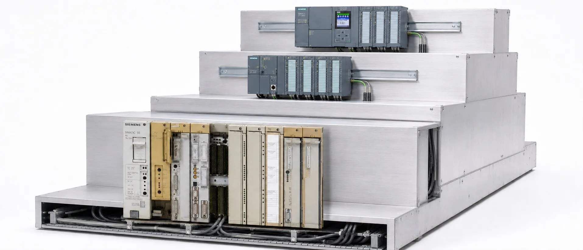
Understanding an existing control system is the first step in proper maintenance
SIMATIC S5, introduced by Siemens in 1979, is a family of programmable logic controllers. It has been used in machine automation, production lines and process control. Assessing an S5 installation today requires attention to the exact hardware, a backup of the running program and the consequences of downtime.
History and product lifecycle
S5 played an important role in the transition from relay-based control to programmable systems. Its range of controller capacities and structured STEP 5 programs supported different applications. The introduction of SIMATIC S7 in 1994 did not mean that existing S5 installations became unusable at that time.
Siemens’ announcement dated 13 October 2020 states that the S5 product lifecycle ended on 30 September 2020. This should not be presented as the date when every model first left production or was last sold. Manufacturer lifecycle status and the availability of used equipment from independent suppliers are separate matters.
Different hardware architectures from 90U to 155U
S5-90U and S5-95U are compact controllers with onboard I/O. S5-100U provides modular expansion through bus units mounted on a standard rail. S5-115U offers different CPU and module options, while S5-135U and S5-155U use central racks and expansion arrangements. S5 controllers should not all be treated as having the same rack design or capabilities.
Even within a family, S5 CPU variants differ in memory, instruction support and communication capabilities. Redundant or fail-safe configurations in certain specialised systems do not make a standard S5 CPU a safety PLC.
Select modules by their complete order numbers
Record the complete order number, hardware revision, CPU type and system configuration. Similar appearance or the shared S5 name does not establish interchangeability. For power supplies, digital inputs, digital outputs and analogue modules, check electrical ratings, addressing and connection arrangements separately.
For an output module, output type and load limits matter alongside channel count. For an analogue module, assess the signal type, measurement range and scaling in the program together. A matching connector does not establish electrical compatibility.
STEP 5 and program blocks
STEP 5 is the S5 programming environment. It uses STL/AWL, LAD/KOP and CSF/FUP representations; not every instruction can be edited graphically. Verify compatibility between the programming device, software version and operating system.
OBs organise execution; OB1 is cyclic. PBs hold program sections, FBs parameterised functions, DBs data, and SBs sequence-control sections where supported. Block capabilities depend on the CPU.
When examining data, read the selected DB and DW number together. DW3 in DB10 and DW3 in DB20 are different data locations.
Programming connections and plant networks are different
Many S5 programming connections use a 20 mA TTY electrical interface and the AS511 protocol. These describe different aspects of the connection. Select a suitable programming cable and converter for the CPU interface; an ordinary USB-to-serial cable should not be assumed sufficient.
SINEC L1, SINEC L2/PROFIBUS, SINEC H1 and serial communication options depend on the CPU variant and communication modules. Do not assume every S5 CPU has built-in PROFIBUS. Establish the protocol, physical interface and network role together.
Important distinctions for memory and battery maintenance
Assess EPROM/EEPROM and other memory modules according to their type and the CPU. Do not assume the cartridge contains the latest program running in RAM. Preserve current DB contents and recipe values separately.
There is no single power-disconnection procedure for replacing batteries across all S5 models. First obtain a verified backup. Qualified personnel should then follow the specific CPU manual and the installation’s safe working arrangements.
Preserve diagnostic evidence before addressing a STOP condition
A STOP indication alone does not establish a defective CPU. Examine supply and field conditions, module indicators and available diagnostic information together. On supporting CPUs, ISTACK/BSTACK records help investigate stoppages and block calls. For example, on the 115U, ZYK can indicate a scan-time overrun and QVZ an I/O timeout.
Avoid an overall reset, arbitrary module replacement or repeated restarts before recording the fault and securing a program backup. After intervention, verify I/O mapping, operating sequences and stopping functions under controlled conditions. A module passing a bench test does not establish that the complete machine operates correctly and safely.
Migrating to S7 requires engineering
Migration to SIMATIC S7 involves the I/O list, specialised modules, communications, operator panel, timing and machine functions alongside the program. Automatic code conversion does not guarantee equivalent operation. Special instructions and data structures may require manual changes or redesign.
The STEP 5–STEP 7 V5.x–TIA Portal route in Siemens’ 2015 guide is a historical workflow. TIA Portal V21 and later cannot directly migrate STEP 7 Classic projects. Siemens describes an intermediate conversion using Migration Tool and TIA Portal V20 or suitable earlier versions. Verify the toolchain against the target CPU and software versions.
Assessing used S5 equipment
For S5 products at Otomasyon AVM, review the complete product code, stated test coverage, included accessories and stock status. Some equipment is used, and sold-out products will not be restocked. This technical article does not constitute a service or commissioning commitment. Technical support and consultancy are not provided for Siemens products.
Related S5 product groups
S5 CPUs and controllers
S5 power supplies
S5 memory modules
S5 communication modules
S5 racks
S5 positioning modules
Supporting topics from other categories
The role of a PLC CPU
PROFIBUS communication
PROFINET architecture
Monitoring with SCADA
The RS-485 interface
Siemens S5 products home
Siemens Automation home
Otomasyon AVM contact information for Siemens products
Sources
Siemens: The 1979 introduction of S5 and renewal resources
Siemens: S5 history and the 30 September 2020 lifecycle milestone
Siemens S5-90U/95U: System, interfaces, memory and battery manual
Siemens S5-100U: Modular architecture and system manual
Siemens S5-115U: STEP 5, blocks, data and diagnostics manual
Siemens S5-135U/155U: Central and expansion system architecture
Siemens STEP 5 V6.6: Projects, comments, symbols and online functions
Siemens: Migration from S5 to S7-1500, 2015 guide
Siemens TIA Portal V21: Project migration options and limitations
Sources checked on 18 October 2026. S5-specific information is based on the manufacturer’s system manuals; use the manual matching the device’s complete order number for any work.